Toyota Sienna Service Manual: A/C ECU Communication Stop
DTC B1262 A/C ECU Communication Stop
DESCRIPTION
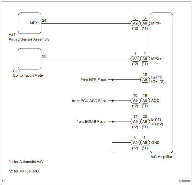
DTC B1262 is output when communication between the A/C amplifier and the multiplex network gateway ECU stops for more than 10 seconds.
|
DTC No. |
DTC Detection Condition |
Trouble Area |
|
B1262 |
A/C ECU communication stops |
|
WIRING DIAGRAM
INSPECTION PROCEDURE
1 CHECK HARNESS AND CONNECTOR (A/C AMPLIFIER - BATTERY)
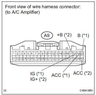
- Disconnect the A9 connector.
- Measure the voltage according to the value(s) in the table below.
Standard voltage
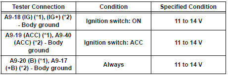
HINT:
*1: for Automatic A/C
*2: for Manual A/C
2 CHECK HARNESS AND CONNECTOR (A/C AMPLIFIER - GROUND)
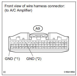
- Measure the resistance according to the value(s) in the table below.
Standard resistance
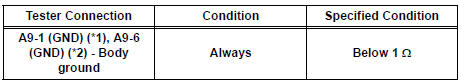
HINT:
*1: for Automatic A/C
*2: for Manual A/C
3 CHECK COMMUNICATION LINE
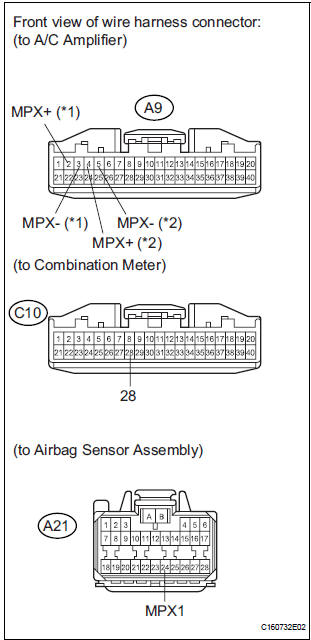
- Disconnect the C10 and A21 connectors.
- Measure the resistance according to the value(s) in the table below.
Standard resistance
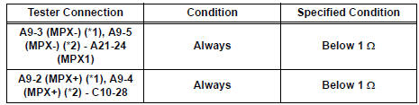
HINT:
*1: for Automatic A/C
*2: for Manual A/C
Result
REPLACE A/C AMPLIFIER
 Rear Door ECU LH Communication Stop
DTC B1217 Rear Door ECU LH Communication Stop
DESCRIPTION
DTC B1217 is output when communication between the power slide door ECU LH
and the multiplex
network gateway ECU stops for more than 10 s ...
 Combination Meter ECU Communication Stop
DTC B1271 Combination Meter ECU Communication Stop
DESCRIPTION
DTC B1271 is output when communication between the combination meter and the
multiplex network
gateway ECU stops for more than 10 se ...
Other materials:
Installation
1. INSTALL FOG LIGHT ASSEMBLY
Install the fog light assembly with the 2 claws and 2
pins.
2. INSTALL FRONT BUMPER ASSEMBLY
3. CONNECT CABLE TO NEGATIVE BATTERY
TERMINAL
4. VEHICLE PREPARATION FOR FOG LIGHT AIMING
5. PREPARATION FOR FOG LIGHT AIMING
6. FOG LIGHT AIMING INSPECT ...
Removal
1. REMOVE FRONT WHEEL
2. REMOVE FRONT AXLE HUB LH NUT
HINT:
(See page AH-4)
SST 09930-00010
3. SEPARATE SPEED SENSOR FRONT LH
HINT:
(See page AH-4)
4. SEPARATE FRONT DISC BRAKE CALIPER
ASSEMBLY LH
HINT:
(See page AH-4)
5. REMOVE FRONT DISC
6. SEPARATE TIE ROD ASSEMBLY LH
HINT:
(See pa ...
Power Source Circuit
DESCRIPTION
Power is supplied to the fold seat control ECU through the L-RR2 SEAT and
R-RR2 SEAT fuses.
WIRING DIAGRAM
INSPECTION PROCEDURE
1 INSPECT FUSE (L-RR2 SEAT, R-RR2 SEAT)
Remove the fuses from the R/B No. 3.
Measure the resistance according to the value(s) in the
...
