Toyota Sienna Service Manual: ABS Warning Light does not Come ON
WIRING DIAGRAM
See page BC-47.
INSPECTION PROCEDURE
1 INSPECT ABS WARNING LIGHT
(a) Disconnect the skid control ECU connector.
(b) Turn the ignition switch to the ON position.
(c) Check that the ABS warning light comes on.
OK: ABS warning light comes on.
HINT: If troubleshooting has been carried out according to the PROBLEM SYMPTOMS TABLE, refer back to the table and proceed to the next step (See page BC-7).

REPLACE BRAKE ACTUATOR ASSEMBLY
2 CHECK HARNESS AND CONNECTOR (BETWEEN SKID CONTROL ECU AND COMBINATION METER ASSEMBLY)
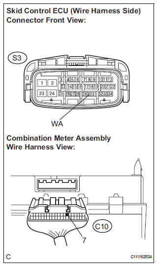
(a) Turn the ignition switch off.
(b) Disconnect the combination meter connector.
(c) Measure the resistance according to the value(s) in the table below.
Standard resistance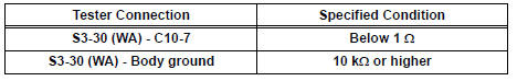

3 INSPECT COMBINATION METER ASSEMBLY
(a) Check the combination meter (See page ME-4).
HINT: If troubleshooting has been carried out according to the PROBLEM SYMPTOMS TABLE, refer back to the table and proceed to the next step (See page BC-7).

END
 ABS Warning Light Remains ON
DESCRIPTION
If any of the following is detected, the ABS warning light remains on.
The skid control ECU connectors are disconnected from the skid control
ECU.
There is a malfunction in the s ...
 Brake Warning Light Remains ON
DESCRIPTION
If the ECU detects a trouble, it turns on the brake warning light at the same
time of prohibiting ABS
control.
At this time, the ECU records a DTC in memory.
Connect terminals TC ...
Other materials:
Installation
1. INSTALL KNOCK CONTROL SENSOR
Install the 2 knock control sensors with the 2 bolts
as shown in the illustration.
Torque: 20 N*m (204 kgf*cm, 15 ft.*lbf)
Connect the 2 knock control sensor connectors.
2. INSTALL INTAKE MANIFOLD
3. INSTALL FUEL MAIN TUBE SUB-ASSEMBLY
4 ...
Engine immobilizer
system
The vehicle’s keys have built-in transponder chips that prevent
the engine from starting if a key has not been previously registered
in the vehicle’s on-board computer.
Never leave the keys inside the vehicle when you leave the vehicle.
This system is designed to help prevent vehicle the ...
Installation
1. INSTALL COMPRESSOR AND MAGNETIC CLUTCH
(a) Using a "TORX" socket wrench (E8), install the
compressor and magnetic clutch with the 2 stud
bolts.
Torque: 10 N*m (102 kgf*cm, 7.4 ft.*lbf)
HINT:
Tighten the stud bolts in the order shown in the
illustration.
(b) Install the c ...
