Toyota Sienna Service Manual: ACIS Control Circuit
DESCRIPTION
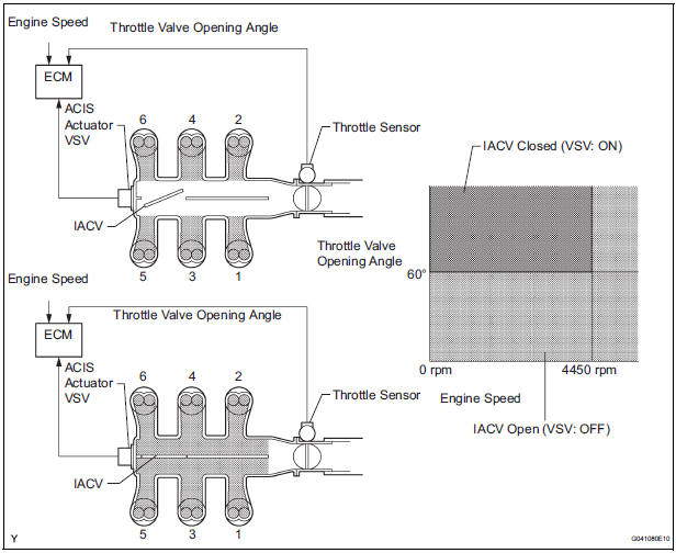
This circuit opens and closes the Intake Air Control Valve (IACV) in response to changes in the engine load in order to increase the intake efficiency (ACIS: Acoustic Control Induction System).
When the engine speed is between 0 and 4450 rpm and the throttle valve opening angle is 60° or more, the ECM supplies current to the VSV (ON status), to close the IACV. Under other conditions, the VSV is usually OFF and the IACV is open.
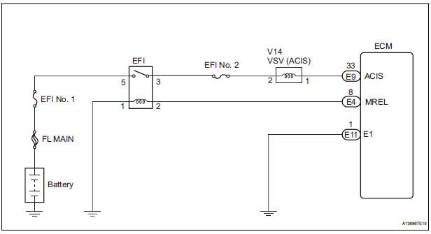
WIRING DIAGRAM
INSPECTION PROCEDURE
1 PERFORM ACTIVE TEST BY INTELLIGENT TESTER (OPERATE VSV FOR ACIS)
(a) Connect the intelligent tester to the DLC3.
(b) Start the engine and turn the intelligent tester on.
(c) Select the following menu items: DIAGNOSIS / ENHANCED OBD II / ACTIVE TEST / INTAKE CTL VSV1. Operate the VSV for AICS.
OK: Operational noise can be heard.

2 CHECK INTAKE AIR CONTROL VALVE (OPERATION)
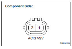
(a) Disconnect the V14 VSV for ACIS connector.
(b) Apply battery voltage between the terminals of the air intake valve connector.
(c) Check the air intake valve operation.
OK: Operational noise can be heard.
(d) Reconnect the VSV for ACIS connector.

3 CHECK HARNESS AND CONNECTOR (VSV FOR ACIS - ECM)
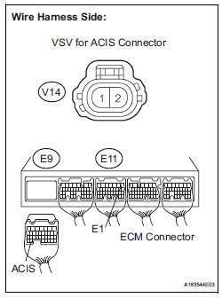
(a) Check the wire harness and connectors between the VSV for ACIS and ECM.
(1) Disconnect the V14 VSV for ACIS connector.
(2) Disconnect the E9 ECM connector.
(3) Measure the resistance according to the value(s) in the table below.
Standard resistance :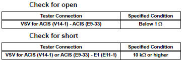
(4) Reconnect the VSV for ACIS connector.
(5) Reconnect the ECM connector.

4 INSPECT FUSE (EFI NO. 2 FUSE)
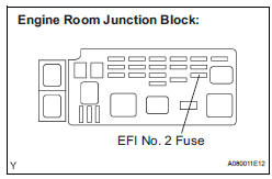
(a) Check the EFI No. 2 fuse.
(1) Remove the EFI No. 2 fuse from the engine room junction block.
(2) Measure the EFI No. 2 fuse resistance.
Standard resistance: Below 1 Ω
(3) Reinstall the EFI No. 2 fuse.

5 CHECK HARNESS AND CONNECTOR (VSV FOR ACIS - EFI RELAY)
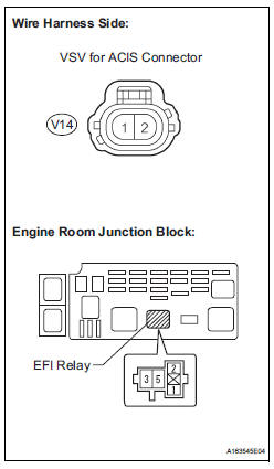
(a) Check the wire harness between the VSV for ACIS connector and EFI relay.
(1) Remove the EFI relay from the engine room junction block.
(2) Disconnect the V14 VSV connector.
(3) Measure the resistance according to the value(s) in the table below.
Standard resistance :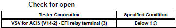
(4) Reinstall the EFI relay.
(5) Reconnect the VSV connector.

CHECK ECM POWER SOURCE CIRCUIT (See page ES-437)
 Cranking Holding Function Circuit
DESCRIPTION
The system detects the ignition switch's starting signal (STSW) and then
supplies current to the starter
until the ECM judges that the engine has started successfully. The purpose is t ...
 Air Intake Control Circuit
DESCRIPTION
The air cleaner is equipped with two inlets, one of which is opened or closed
by the Air Intake Control
Valve (AICV). This system reduces intake noise and increases engine power at
l ...
Other materials:
Opening the back door from outside the vehicle
Back door opener
Raise the back door while
pressing the back door opener
to release the lock to open the
back door.
Wireless remote control (vehicles with power back door)
Press and hold the switch to open/close the power back door
Vehicles without a smart key
system
Vehicl ...
Precaution for cooling fan system
NOTICE: • When the ignition switch is turned off and the
engine temperature is high, the cooling fans may
operate for approximately 3 minutes. • After turning the ignition switch
off, keep hands
and objects away from the fans when they are operating.
HINT:
If all of the following a ...
Short to GND in Front Passenger Side Squib
2nd Step Circuit
DTC B1187/55 Short to GND in Front Passenger Side Squib
2nd Step Circuit
DESCRIPTION
The front passenger side squib 2nd step circuit consists of the center airbag
sensor assembly and the
front passenger airbag assembly.
The circuit instructs the SRS to deploy when deployment conditions are ...
