Toyota Sienna Service Manual: Air Inlet Damper Control Servo Motor Circuit
DESCRIPTION
The air inlet control servo motor is controlled by the A/C amplifier and moved to the desired position.
The air inlet control servo motor switches the air inlet mode by rotating
(normal, reverse) with electrical
power from the A/C amplifier. This controls intake air and changes the mode
between
"RECIRCULATION", "FRESH", and "HALF-RECIRCULATION".
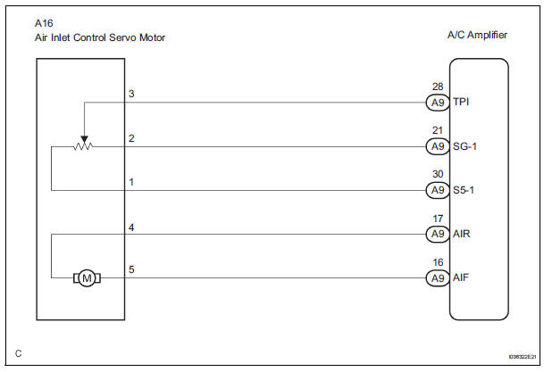
WIRING DIAGRAM
INSPECTION PROCEDURE
1 READ VALUE OF INTELLIGENT TESTER
(a) Connect the intelligent tester to the DLC3.
(b) Turn the ignition switch to the ON position and turn the intelligent tester main switch on.
(c) Select the items below in the DATA LIST, and read the display on the intelligent tester.
DATA LIST / AIR CONDITIONER 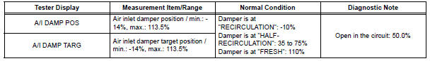
OK: When the target position is "RECIRCULATION" (- 10%), the actual opening angle is 19.0% or less.
When the target position is "FRESH" (110%), the actual opening angle is 81.0% or more.
Result 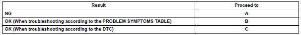

2 PERFORM ACTIVE TEST BY INTELLIGENT TESTER
(a) Remove the glove box to see and check the recirculation damper operation.
(b) Connect the intelligent tester to the DLC3.
(c) Turn the ignition switch to the ON position and turn the intelligent tester main switch on.
(d) Select the item below in the ACTIVE TEST and then check that the damper operates.
ACTIVE TEST / AIR CONDITIONER 
OK: Lever turns from "RECIRCULATION" side to "FRESH" side smoothly.
Lever turns from "FRESH" side to "RECIRCULATION" side smoothly.
Result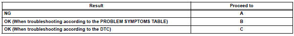

3 PERFORM ACTUATOR CHECK
(a) Remove the glove box to see and check the recirculation damper operation.
(b) Enter the actuator check mode (See page AC-15).
(c) Press the DEF switch and check the operation of the
recirculation damper.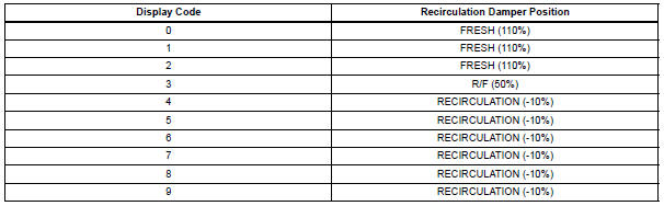
OK: Recirculation damper position changes in accordance with each display code.
Result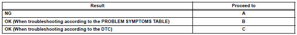

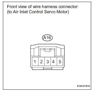
4 INSPECT AIR INLET CONTROL SERVO MOTOR
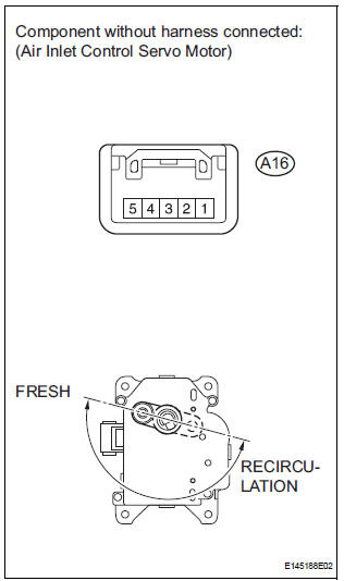
(a) Remove the air inlet control servo motor.
(b) Disconnect the connector from the air inlet control servo motor.
(c) Connect the positive (+) lead from the battery to terminal 5 and the negative (-) lead to terminal 4, then check that the lever turns to the "FRESH" position smoothly.
OK: Lever turns to "FRESH" position smoothly.
(d) Connect the positive (+) lead from the battery to terminal 4 and the negative (-) lead to terminal 5, then check that the lever turns to the "RECIRCULATION" position smoothly.
OK: Lever turns to "RECIRCULATION" position smoothly.

5 CHECK HARNESS AND CONNECTOR (AIR INLET CONTROL SERVO MOTOR - A/C AMPLIFIER)
(a) Disconnect the connector from the A/C amplifier.
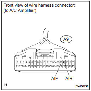
(b) Measure the resistance according to the value(s) in the table below.
Standard resistance 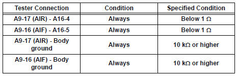

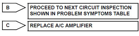
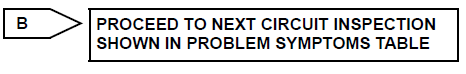
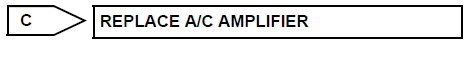
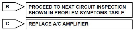
REPLACE A/C AMPLIFIER
 Air Mix Damper Control Servo Motor Circuit (Passenger Side)
DESCRIPTION
The air mix control servo motor (air mix damper servo sub-assembly) is
controlled by the A/C amplifier.
The air mix control servo motor moves the air mix damper by rotating (normal, ...
 Air Outlet Damper Control Servo Motor Circuit
DESCRIPTION
This circuit turns the servo motor and changes each damper position by
receiving the signals from the A/
C amplifier.
The air outlet damper servo motor switches the air outlet mode ...
Other materials:
Camshaft Position "A" - Timing Over
HINT:
If DTC P0011, P0012, P0021 or P0022 is present, check the VVT (Variable Valve
Timing) system.
DESCRIPTION
Refer to DTC P0010 (See page ES-75).
DTC No.
DTC Detection Condition
Trouble Area
P0011
P0021
Advanced cam timing:
With warm engine and engine spee ...
Camshaft Position "B" - Timing Over
HINT:
If DTC P0014, P0015, P0024 or P0025 is present, check the VVT (Variable Valve
Timing) system.
DESCRIPTION
Refer to DTC P0013 (See page ES-87).
MONITOR DESCRIPTION
DTC P0014 and P0024
The ECM compares current valve timing with target valve timing, while the
engine is running a ...
Rear wiper rubber
COMPONENTS
REMOVAL
1. REMOVE REAR WIPER BLADE ASSEMBLY
Remove the rear wiper arm head cap from the rear
wiper arm.
Raise the rear wiper blade to the position as shown
in the illustration where the meshing of the claw is
disengaged with the click sound.
NOTICE:
...
