Toyota Sienna Service Manual: Air Inlet Damper Position Sensor Circuit
DESCRIPTION
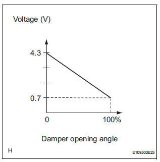
This sensor detects the position of the air inlet control servo motor and sends the appropriate signals to the A/C amplifier. The position sensor is built in the air inlet control servo motor.
The position sensor's resistance changes as the air inlet control servo motor arm moves.
It outputs voltage (5 V) that is input to terminal 1 and terminal 3 via the variable resistor, and then to the A/ C amplifier.
The A/C amplifier determines the arm position based on the input voltage from
the position sensor. 
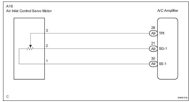
WIRING DIAGRAM
INSPECTION PROCEDURE
1 READ VALUE OF INTELLIGENT TESTER
(a) Connect the intelligent tester to the DLC3.
(b) Turn the ignition switch to the ON position and turn the intelligent tester main switch on.
(c) Select the items below in the DATA LIST, and read the display on the intelligent tester.
DATA LIST / AIR CONDITIONER 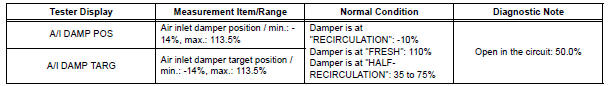
OK: The display is as specified in the normal condition column.
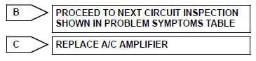
Result 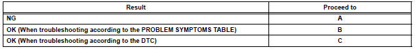

2 INSPECT AIR INLET CONTROL SERVO MOTOR
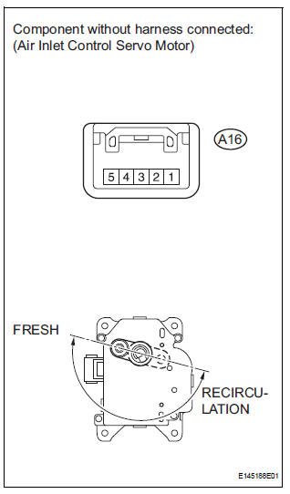
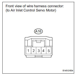
(a) Remove the air inlet control servo motor.
(b) Disconnect the connector from the air inlet control servo motor.
(c) Measure the resistance according to the value(s) in the table below.
Standard resistance 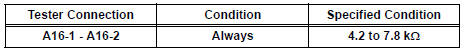
(d) Measure the resistance according to the value(s) in the table below.
Standard resistance 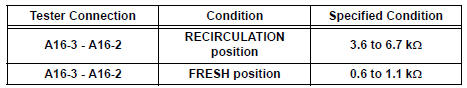
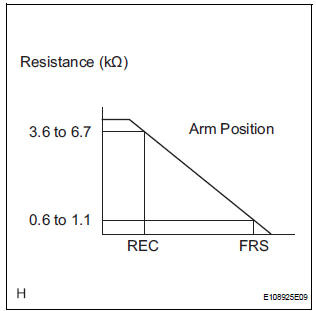
(e) As the air inlet control servo motor moves from RECIRCULATION to FRESH, the resistance decreases gradually without interruption.

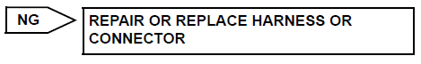
3 CHECK HARNESS AND CONNECTOR (AIR INLET CONTROL SERVO MOTOR - A/C AMPLIFIER)
(a) Disconnect the connector from the A/C amplifier.
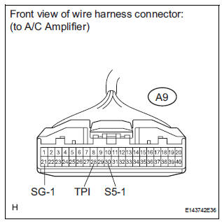
(b) Measure the resistance according to the value(s) in the table below.
Standard resistance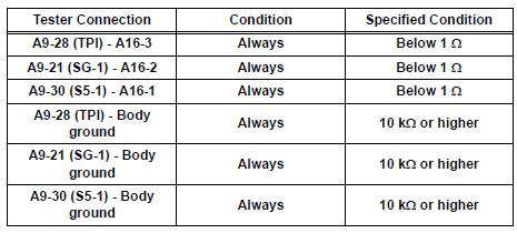

Standard resistance
 Air Mix Damper Position Sensor Circuit (Passenger Side)
DESCRIPTION
This sensor detects the position of the air mix control servo motor (air mix
damper) and sends the
appropriate signals to the A/C amplifier. The position sensor is built in the
a ...
 Air Outlet Damper Position Sensor Circuit
DESCRIPTION
This sensor detects the position of the air outlet control servo motor and
sends the appropriate signals to
the A/C amplifier. The position sensor is built in the air outlet contro ...
Other materials:
Sound setting
Display the “Phone/Message Settings” screen.
Select “Sound Settings” on the “Phone/Message Settings” screen.
Set the desired ringtone.
Adjust the ringtone volume.
Adjust the message readout
volume.
Set the desired incoming
SMS/MMS tone.
Adjust the incoming SMS ...
Adjustment
HINT:
If the malfunction does not disappear by following the
procedure in ADJUSTMENT and the rear No. 2 seat
assembly needs to be replaced, do not disassemble the rear
No. 2 seat assembly.
1. ADJUST FRONT LEG
HINT:
Perform the following procedure if the inner leg does not
lock.
P ...
Eject Error/ Elevator Error/ Clamp Error/ Eject Error/ Elevator Error/ Clamp
Error
DTC 62-45 Eject Error
DTC 62-51 Elevator Error
DTC 62-52 Clamp Error
DTC 63-45 Eject Error
DTC 63-51 Elevator Error
DTC 63-52 Clamp Error
DESCRIPTION
DTC No.
DTC Detecting Condition
Trouble Area
62-45
Disc cannot be ejected.
Radio receiver
62-5 ...
