Toyota Sienna Service Manual: Automatic Light Control Sensor Circuit
DESCRIPTION
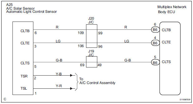
The Multiplex network body ECU receives the signal from the automatic light control sensor.
HINT: DTC code is output when malfunction of automatic light control sensor or open or short of automatic light control sensor circuit occurs.
WIRING DIAGRAM
INSPECTION PROCEDURE
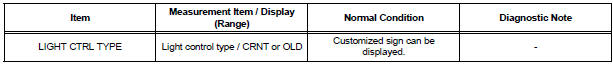
1 READ VALUE OF INTELLIGENT TESTER
- Connect the intelligent tester to DLC3.
- Turn the ignition switch ON and push the intelligent tester main switch ON.
- Select the items below in the DATA LIST, and read the displays on the intelligent tester
BODY NO.1:
2 CHECK HARNESS AND CONNECTOR (MULTIPLEX NETWORK BODY ECU - AUTOMATIC LIGHT CONTROL SENSOR)
- Check for open or short circuit in the harness and the connector between the terminal 6 of the automatic light control sensor and the terminal B6-6 of the multiplex network body ECU.
- Check for open or short circuit in the harness and the connector between the terminal 3 of the automatic light control sensor and the terminal B6-4 of the multiplex network body ECU.
- Check for open or short circuit in the harness and the connector between the terminal 5 of the automatic light control sensor and the terminal B6-5 of the multiplex network body ECU
3 INSPECT INSTRUMENT PANEL JUNCTION BLOCK ASSEMBLY
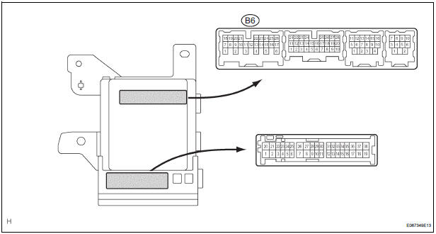
- Measure voltage between the terminal B6-4 and the terminal B6-6 of the multiplex network body ECU in the instrument panel junction block assembly.
Voltage

PROCEED TO NEXT CIRCUIT INSPECTION SHOWN IN PROBLEM SYMPTOMS TABLE
 Light Control Switch Circuit
DESCRIPTION
This circuit detects the state of the headlight dimmer switch.
WIRING DIAGRAM
INSPECTION PROCEDURE
1 READ VALUE OF INTELLIGENT TESTER
Connect the intelligent tester to DLC3.
...
 Door Courtesy Switch Circuit
DESCRIPTION
The Multiplex network body ECU detects the condition of the door courtesy
switch assembly.
WIRING DIAGRAM
INSPECTION PROCEDURE
1 READ VALUE OF INTELLIGENT TESTER
Connect the ...
Other materials:
Terminals of ECU
1. CHECK POWER BACK DOOR ECU
Disconnect the P13 and P14 ECU connectors, and
check the voltage or resistance of each terminal of
the wire harness side connectors
If the result is not as specified, there may be a
malfunction on the wire harness side.
Reconnect the ECU connector ...
Power Windows do not Operate at All
DESCRIPTION
If all of the door windows do not operate, no power may be supplied to the
power window master switch or
the power window master switch itself may have a malfunction.
WIRING DIAGRAM
INSPECTION PROCEDURE
1 INSPECT FUSE (PWR, ECU-IG, AM1)
Remove the fuses from the driver sid ...
Initialization
1. ZERO POINT CALIBRATION
NOTICE:
Make sure that the front passenger seat is not
occupied before performing the operation.
HINT:
Perform the zero point calibration and sensitivity check if
any of the following conditions occur.
The occupant classification ECU is replaced.
A ...
