Toyota Sienna Service Manual: Back Sonar Sensor RH Circuit
DESCRIPTION
An ultrasonic sensor consists of a sensor portion that transmits and receives ultrasonic waves and a preamplifier that amplifies them. The ultrasonic sensor outputs the ultrasonic waves and sends the received signals to the clearance warning ECU.
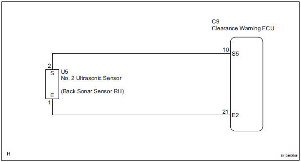
WIRING DIAGRAM
INSPECTION PROCEDURE
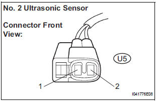
1 INSPECT NO. 2 ULTRASONIC SENSOR
- Remove the No. 2 ultrasonic sensor.
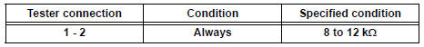
- Measure the resistance according to the value(s) in the table below.
Standard resistance
2 CHECK HARNESS AND CONNECTOR (CLEARANCE WARNING ECU - NO. 2 ULTRASONIC SENSOR)
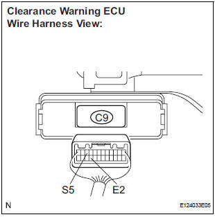
- Disconnect the C9 connector from the clearance warning ECU.
- Disconnect the U5 connector from the No. 2 ultrasonic sensor.
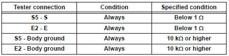
- Measure the resistance according to the value(s) in the table below.
Standard resistance
PROCEED TO NEXT CIRCUIT INSPECTION SHOWN IN PROBLEM SYMPTOMS TABLE
 Back Sonar Sensor LH Circuit
DESCRIPTION
An ultrasonic sensor consists of a sensor portion that transmits and receives
ultrasonic waves and a preamplifier
that amplifies them. The ultrasonic sensor outputs the ultrasonic wave ...
 Front Clearance Sonar Sensor LH Circuit
DESCRIPTION
An ultrasonic sensor consists of a sensor portion that transmits and receives
ultrasonic waves and a preamplifier
that amplifies them. The ultrasonic sensor outputs the ultrasonic wave ...
Other materials:
Electronic control
(a) REMOVAL AND INSTALLATION OF BATTERY TERMINAL
REMOVAL AND INSTALLATION OF BATTERY TERMINAL
NOTICE: Certain systems need to be initialized
after
disconnecting and reconnecting the cable from
the negative (-) battery terminal.
(1) Before performing electronic work, disconnect
the ...
Glossary of sae and Toyota terms
This glossary lists all SAE-J1930 terms and abbreviations
used in this manual in compliance with SAE
recommendations, as well as their TOYOTA equivalents.
...
Data list / active test
1. DATA LIST
(a) While the intelligent tester is connected to the DLC3
with the ignition switch in the ON position, the ABS
data list can be displayed. Follow the prompts on
the tester screen to access the DATA LIST.
2. ACTIVE TEST
HINT:
Performing the ACTIVE TEST using the intelligent te ...
