Toyota Sienna Service Manual: Brake Switch "A" Circuit
DTC P0571 Brake Switch "A" Circuit
DESCRIPTION
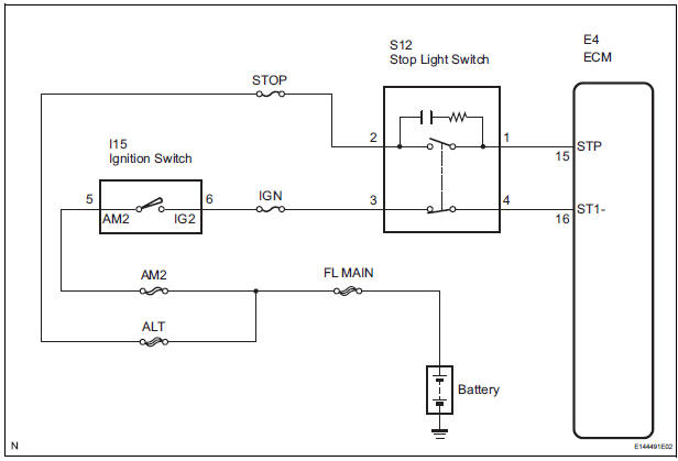
When the brake pedal is depressed, the stop light switch sends a signal to the ECM. When the ECM receives this signal, it cancels the cruise control. The fail-safe function operates to enable normal driving even if there is a malfunction in the stop light signal circuit. The cancellation condition occurs when voltage is applied to terminal STP. When the brake is applied, voltage is normally applied to terminal STP of the ECM through the STOP fuse and the stop light switch, and the ECM turns the cruise control off.
|
DTC No. |
DTC Detection Condition |
Trouble Area |
|
P0571 |
Voltage of STP terminal and that of ST1- terminal of ECM are less than 1 V for 0.5 sec. or more. |
|
WIRING DIAGRAM
INSPECTION PROCEDURE
1 READ VALUE OF INTELLIGENT TESTER
- Connect the intelligent tester to the DLC3.
- Turn the ignition switch to the ON position, and turn the intelligent tester main switch on.
- Check the DATA LIST for proper functioning of the stop light switch.
ECM (Cruise control):
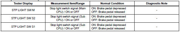
OK: When the brake pedal is operated, the display changes as shown above.
REPLACE ECM
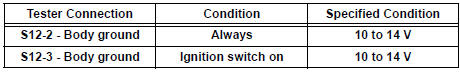
2 CHECK HARNESS AND CONNECTOR (STOP LIGHT SWITCH - BATTERY)
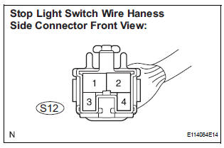
- Disconnect the S12 connector from the stop light switch.
- Measure the voltage according to the value(s) in the table below.
Standard voltage
3 INSPECT STOP LIGHT SWITCH
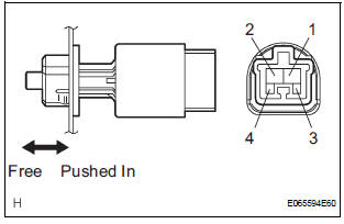
- Remove the stop light switch.
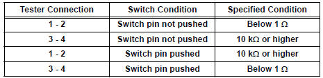
- Measure the resistance according to the value(s) in the table below.
Standard resistance
- Install the stop light switch.
4 CHECK ECM
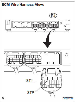
- Reconnect the S12 stop light switch connector.
- Disconnect the E4 connector from the ECM.
- Turn the ignition switch to the ON position.
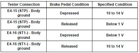
- Measure the voltage according to the value(s) in the table below.
Standard voltage
REPLACE ECM
 Vehicle Speed Sensor Malfunction
DTC P0500 Vehicle Speed Sensor Malfunction
DTC P0503 Vehicle Speed Sensor Circuit Malfunction
DESCRIPTION
The cruise control system uses the same vehicle speed signal that is sent to
the ECM for ...
 Input Signal Circuit Malfunction
DTC P0607 Input Signal Circuit Malfunction
DESCRIPTION
This DTC indicates internal abnormalities of the ECM.
DTC No.
Detection Item
Trouble Area
P0607
The E ...
Other materials:
Memory recall function
Each electronic key can be registered to recall your preferred driving
position.
Registering procedure
Record your driving position to button “1” or “2” before performing
the following:
Carry only the key you want to register, and then close the driver’s
door.
If 2 or more keys ar ...
Laser Sensor Power Source Circuit
DESCRIPTION
This circuit provides power to the laser sensor. The laser sensor emits radio
waves towards an object in
front and measures the distance and direction of the object by receiving the
beam reflections. Based on
the reflections, the sensor calculates the difference in speed between t ...
Diagnostic trouble code chart
If a trouble code is displayed during the DTCs check (sensor
check), check the circuit listed for the code in the table below
(Proceed to the page given for that circuit).
AIR CONDITIONING SYSTEM
HINT:
*1: If the cabin temperature is approximately -18.6°C (-
3.7°F) or lo ...
