Toyota Sienna Service Manual: Brake Switch "B" Circuit High

DESCRIPTION
The purpose of this circuit is to prevent the engine from stalling while driving in lock-up condition when brakes are suddenly applied.
When the brake pedal is depressed, this switch sends a signals to the ECM. Then the ECM cancels the operation of the lock-up clutch while braking is in progress.
MONITOR DESCRIPTION
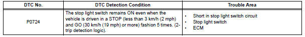
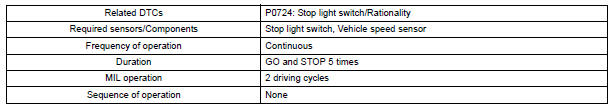
This DTC indicates that the stop light switch remains on. When the stop light switch remains ON during "stop and go" driving, the ECM interprets this as a fault in the stop light switch and the MIL comes on and the ECM stores the DTC. The vehicle must stop (less than 3 km/h (2 mph)) and go (30 km/h (19 mph) or more) 5 times for two driving cycles in order to detect a malfunction.
MONITOR STRATEGY
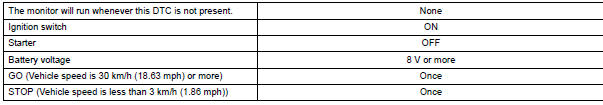
TYPICAL ENABLING CONDITIONS
TYPICAL MALFUNCTION THRESHOLDS

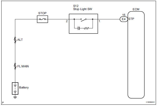
WIRING DIAGRAM
INSPECTION PROCEDURE
1 READ VALUE OF DATA LIST
HINT: Using the intelligent tester to read the DATA LIST allows the values or states of switches, sensors, actuators and other items to be read without removing any parts. This nonintrusive inspection can be very useful because intermittent conditions or signals may be discovered before parts or wiring is disturbed. Reading the DATA LIST information early in troubleshooting is one way to save diagnostic time.
(a) Warm up the engine.
(b) Turn the ignition switch off.
(c) Connect the OBD II scan tool or intelligent tester together with the CAN VIM (controller area network vehicle interface module) to the DLC3.
(d) Turn the ignition switch to the ON position.
(e) Turn on the tester.
(f) Select the item "DIAGNOSIS / ENHANCED OBD II / DATA LIST".
(g) According to the display on the tester, read the "DATA
LIST". 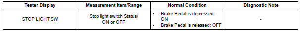
| NOTICE: In the table below, the value listed under "Normal Condition" are reference values. Do not depend solely on these reference values when deciding whether apart is faulty or not. |
Result 

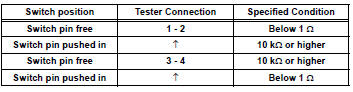
2 INSPECT STOP LIGHT SWITCH ASSEMBLY
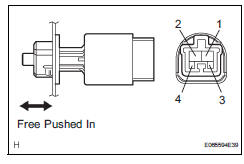
(a) Remove the stop light switch assembly.
(b) Measure the resistance according to the value(s) in the table below.
Standard resistance

3 CHECK HARNESS AND CONNECTOR (STOP LIGHT SWITCH ASSEMBLY - ECM)
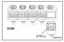
(a) Install the stop light switch assembly.
(b) Measure the voltage according to the value(s) in the table below when the brake pedal is depressed and released.
Standard voltage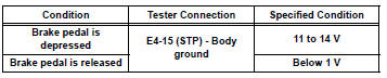

REPLACE ECM
 Turbine Speed Sensor Circuit No Signal
DESCRIPTION
This sensor detects the rotation speed of the input turbine. By comparing the
input turbine speed signal
(NT) with the counter gear speed sensor signal (NC), the ECM detects the sh ...
 Torque Converter Clutch Solenoid Performance
(Shift Solenoid Valve DSL)
Torque Converter Clutch Solenoid Performance
(Shift Solenoid Valve DSL)
SYSTEM DESCRIPTION
The ECM uses the signals from the throttle position sensor, air-flow meter,
turbine (input) speed sensor,
intermediate (counter) shaft speed sensor and crankshaft position s ...
Other materials:
Inspection
1. INSPECT FRONT DRIVE SHAFT ASSEMBLY LH
(a) Check that there is no remarkable play in the radial
direction of the outboard joint.
(b) Check that the inboard joint slides smoothly in the
thrust direction.
(c) Check that there is no remarkable play in the radial
direction of the inboard ...
Basic repair hint
(a) HINTS ON OPERATIONS
BASIC REPAIR HINT
1
Attire
• Always wear a clean uniform.
• Hat and safety shoes must be worn.
2
Vehicle protection
Prepare a grille cover, fender cover, seat cover and floor mat before
starting the
operation.
3
...
Throttle Actuator Control System
DTC P2111 Throttle Actuator Control System - Stuck Open
DTC P2112 Throttle Actuator Control System - Stuck
Closed
DESCRIPTION
The throttle actuator is operated by the ECM, and opens and closes the
throttle valve using the gears.
The opening angle of the throttle valve is detected by the Thr ...
