Toyota Sienna Service Manual: Calibration
1. SELECT COMPASS DISPLAY MODE
- The MODE switch allows you to select the Display or Non-display mode of the compass.
HINT: In compass display mode, the display indicates outside temperature/average fuel consumption/ instantaneous fuel consumption/distance to empty with compass.
2. SET ZONE
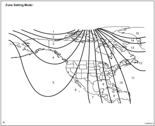
- Deviation between the "magnetic north" and "actual
north" differs depending on the location. Therefore,
adjustment of the magnetism is required. Since the
magnetic condition differs depending on the area
where the vehicle is used, it is necessary for each
user to set the zone (Refer to Zone Setting Map).
The zone setting can be changed using the MODE switch of the accessory meter assembly.
3. PERFORM CALIBRATION
- Because each vehicle has its own magnetic field,
calibration should be performed for each vehicle.
This compass function is used when storing the record of the vehicle's magnetic field.
4. WHEN COMPASS IS MAGNETIZED
- A compass could be magnetized during shipping by vessels or freight cars. Therefore, make sure to perform calibration and ensure that calibration is performed properly before delivery. If it cannot be done (cannot be completed in spite of driving around several times), it may be caused by magnetization. Demagnetize the vehicle using a demagnetizer and perform calibration again.
5. SET COMPASS
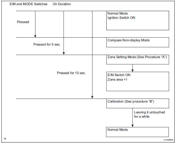
6. ZONE SETTING MODE (PROCEDURE "A")
- Pressing the E/M and MODE switches
simultaneously for 5 seconds in the normal mode
will activate the zone setting mode. A number (1 to
15) is displayed on the compass display.
NOTICE: In the initial state, "VAR" is displayed.
- The displayed number increases by 1 every time the E/M switch is pressed. Referring to the map, check the number for the area where the vehicle will be used and set the zone number.
- Leave it untouched for several seconds after setting and check that the compass display shows an azimuthal direction (N, NE, E, SE, S, SW, W or NW) or "CAL".
7. CALIBRATION SETTING MODE (PROCEDURE "B")
- Pressing the E/M and MODE switches simultaneously for 10 seconds in the normal mode will activate the calibration setting mode.
- Drive the vehicle at a slow speed of 8 km/h (5 mph) or less in the circular direction.
- Driving around the circle 1 to 3 times will display the azimuthal direction on the display, completing the calibration.
NOTICE: After the calibration is completed, it is not necessary to perform the above procedures unless the magnetic field strength is drastically changed. If this happens, the azimuthal display will be changed to "CAL".
 Accessory meter
COMPONENTS
...
 Removal
1. REMOVE ROOF CONSOLE BOX ASSEMBLY
2. REMOVE ACCESSORY METER ASSEMBLY
Using torx socket wrench (T10), remove the 5
screws and accessory meter assembly.
...
Other materials:
Pressure Control Solenoid "A" Electrical (Shift
Solenoid Valve SL1)
DESCRIPTION
Shifting from 1st to 5th is performed in combination with "ON" and "OFF"
operation of the shift solenoid
valves SL1, SL2, SL3, S4 and SR which are controlled by the ECM. If an open or
short circuit occurs in
either of the shift solenoid valves, the ECM cont ...
High Temperature
DTC 44-47 High Temperature
DESCRIPTION
DTC No.
DTC Detecting Condition
Trouble Area
44-47
Sensor detects that DVD unit temperature is high.
(Over 80C)
Television display assembly
INSPECTION PROCEDURE
HINT:
After the inspection is completed, ...
Wiper Signal Circuit
DESCRIPTION
The distance control ECU detects wiper operation. If the windshield wipers
operate in the HI or LO mode,
the cruise control is canceled and the warning sound "pong" is emitted once. In
addition, the following
warnings will continue until the cruise control main switch is ...
