Toyota Sienna Service Manual: Camshaft Position "A" - Timing Over
HINT:
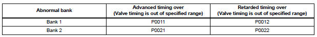
If DTC P0011, P0012, P0021 or P0022 is present, check the VVT (Variable Valve Timing) system.
DESCRIPTION
Refer to DTC P0010 (See page ES-75).
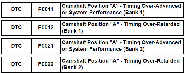
| DTC No. | DTC Detection Condition | Trouble Area |
| P0011 P0021 | Advanced cam timing: With warm engine and engine speed of between 500 rpm and 4000 rpm, all conditions (a), (b) and (c) are met (1 trip detection logic): (a) Difference between target and actual intake valve timings is more than 5° CA (Crankshaft Angle) for 4.5 seconds (b) Current intake valve timing is fixed (timing changes less than 5° CA in 5 seconds) (c) Variations in VVT controller timing are more than 19° CA of maximum delayed timing (advanced) |
|
| P0012 P0022 | Retarded cam timing: With warm engine and engine speed of between 500 rpm and 4000 rpm, all conditions (a), (b) and (c) are met (2 trip detection logic): (a) Difference between target and actual intake valve timings is more than 5° CA (Crankshaft Angle) for 4.5 seconds (b) Current intake valve timing is fixed (timing changes less than 5° CA in 5 seconds) (c) Variations in VVT controller timing is 19° CA or less of maximum delayed timing (retarded) |
|
MONITOR DESCRIPTION
The ECM optimizes the intake valve timing using the VVT (Variable Valve Timing) system to control the intake camshaft. The VVT system includes the ECM, the Oil Control Valve (OCV) and the VVT controller.
The ECM sends a target duty-cycle control signal to the OCV. This control signal regulates the oil pressure applied to the VVT controller. The VVT controller can advance or retard the intake camshaft.
If the difference between the target and actual intake valve timings is large, and changes in actual intake valve timing are small, the ECM interprets this as the VVT controller stuck malfunction and sets a DTC.
Example: A DTC will be set when the following conditions 1), 2) and 3) are met:
1) The difference between the target and actual intake valve timings is more than 5° CA (Crankshaft Angle) and the condition continues for more than 4.5 seconds.
2) It takes 5 seconds or more to change the valve timing by 5° CA.
3) After above conditions 1) and 2) are met, the OCV is forcibly activated 63 times or more.
DTCs P0011 and P0021 (Advanced Cam Timing) are detected with 1 trip detection logic.
DTCs P0012 and P0022 (Retarded Cam Timing) are detected with 2 trip detection logic.
These DTCs indicate that the VVT controller cannot operate properly due to OCV malfunctions or the presence of foreign objects in the OCV.
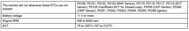
The monitor will not run unless the following conditions are met:
- The engine is warm (the engine coolant temperature is 75°C [167°F] or more).
- The vehicle has been driven at more than 40 mph (64 km/h) for 3 minutes.
- The engine has idled for 3 minutes.
MONITOR STRATEGY
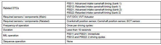
TYPICAL ENABLING CONDITIONS
TYPICAL MALFUNCTION THRESHOLDS
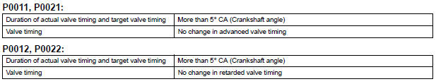
If the difference between the target and actual camshaft timings is greater than the specified value, the ECM operates the VVT actuator.
Then, the ECM monitors the camshaft timing change for 5 seconds.
WIRING DIAGRAM
Refer to DTC P0010 (See page ES-77).
INSPECTION PROCEDURE
HINT:
- If DTC P0011 or P0012 is displayed, check the bank 1 VVT system circuit.
- Bank 1 refers to the bank that includes cylinder No. 1.
- If DTC P0021 or P0022 is displayed, check the bank 2 VVT system circuit.
- Bank 2 refers to the bank that does not include cylinder No. 1.
- Read freeze frame data using the intelligent tester. The ECM records vehicle and driving condition information as freeze frame data the moment a DTC is stored. When troubleshooting, freeze frame data can be helpful in determining whether the vehicle was running or stopped, whether the engine was warmed up or not, whether the air-fuel ratio was lean or rich, as well as other data recorded at the time of a malfunction.
1 CHECK ANY OTHER DTCS OUTPUT (IN ADDITION TO DTC P0011, P0012, P0021 OR P0022)
(a) Connect the intelligent tester to the DLC3.
(b) Turn the ignition switch to the ON position and turn the tester on.
(c) Select the following menu items: DIAGNOSIS / ENHANCED OBD II / DTC INFO / CURRENT CODES.
(d) Read the DTCs.
Result 
HINT:
If any DTCs other than P0011, P0012, P0021 or P0022 are output, troubleshoot those DTCs first.


2 PERFORM ACTIVE TEST BY INTELLIGENT TESTER (OPERATE OCV)
(a) Connect the intelligent tester to the DLC3.
(b) Start the engine and turn the tester on.
(c) Warm up the engine.
(d) Select the following menu items on the tester: DIAGNOSIS / ENHANCED OBD II / ACTIVE TEST / VVT CTRL B1.
(e) Check the engine speed while operating the Oil Control Valve (OCV) using the tester.
OK 


3 CHECK WHETHER DTC OUTPUT RECURS (DTC P0011, P0012, P0021 OR P0022)
(a) Connect the intelligent tester to the DLC3.
(b) Turn the ignition switch to the ON position and turn the tester on.
(c) Clear the DTCs (See page ES-39).
(d) Start the engine and warm it up.
(e) Select the check mode using the tester (See page ES- 43).
(f) Drive the vehicle for more than 10 minutes.
(g) Read the DTCs using the tester.
OK: No DTC outputs.


SYSTEM IS OK
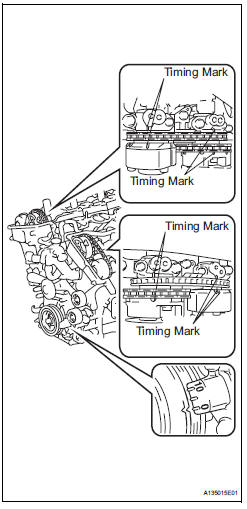
4 CHECK VALVE TIMING (CHECK FOR LOOSE AND JUMPED TEETH ON TIMING CHAIN)
(a) Remove the cylinder head covers RH and LH.
(b) Turn the crankshaft to align the timing marks of the crankshaft.
(c) Align the notch of the crankshaft pulley to the "0" position.
(d) Check if the timing marks of the camshaft pulley and camshaft bearing cap align.
(e) Turn the crankshaft clockwise by 360° if the timing marks do not align. Check if they align once again.
OK: The timing marks of the camshaft pulley and the camshaft bearing cap align when the notch of the crankshaft pulley is in the "0" position.


5 INSPECT CAMSHAFT TIMING OIL CONTROL VALVE ASSEMBLY (OCV)
(a) Remove the camshaft timing oil control valve (OCV).
(b) Measure the resistance according to the value(s) in the table below.
Standard resistance 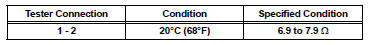
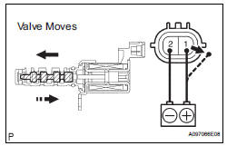
(c) Apply the positive battery voltage to terminal 1 and the negative battery voltage to terminal 2. Check the valve operation.
OK: Valve moves quickly.
(d) Reinstall the OCV.

6 CHECK OIL PIPE AND OIL CONTROL VALVE FILTER
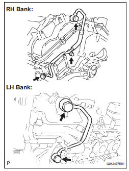
(a) Remove the oil pipe No. 1 or oil pipe assembly.
(b) Remove the oil control valve filter.
(c) Check that the filter and pipe are not clogged.
OK: The filter and pipe are not clogged.

7 REPLACE CAMSHAFT TIMING GEAR ASSEMBLY

8 CHECK WHETHER DTC OUTPUT RECURS
(a) Connect the intelligent tester to the DLC3.
(b) Turn the ignition switch to the ON position and turn the tester on.
(c) Clear the DTCs (See page ES-39).
(d) Start the engine and warm it up.
(e) Select the check mode using the tester (See page ES- 43).
(f) Drive the vehicle for more than 10 minutes.
(g) Confirm that no DTC is set using the tester.
OK: No DTC output.
HINT:
DTC P0011, P0012, P0021 or P0022 is output when foreign objects in engine oil are caught in some parts of the system. These codes will stay output even if the system returns to normal after a short time. These foreign objects are then captured by the oil filter, thus eliminating the source of the problem.


SYSTEM IS OK
 Camshaft Position "A" Actuator Circuit
DESCRIPTION
The Variable Valve Timing (VVT) system includes the ECM, Oil Control Valve
(OCV) and VVT controller.
The ECM sends a target duty-cycle control signal to the OCV. This control sig ...
 Camshaft Position "B" Actuator Circuit
DESCRIPTION
The Variable Valve Timing (VVT) system includes the ECM, OCV and VVT
controller. The ECM sends a
target duty-cycle control signal to the OCV. This control signal regulates the
oi ...
Other materials:
No Master/ Connection Check Error
DTC 01-D6 No Master
DTC 01-D7 Connection Check Error
DESCRIPTION
HINT:
*1: Even if no fault is present, this trouble code may be stored
depending on the battery condition or
engine start voltage.
*2: When 210 seconds have elapsed after disconnecting the power
supply ...
For vehicles equipped with traction control (trac) system
When using a 2-wheel drum tester such as a
speedometer tester or chassis dynamometer, etc., or
jacking up the front wheels and driving the wheels,
always push in the TRAC cut ("TRAC OFF") switch and
turn the TRAC system OFF.
FOR VEHICLES EQUIPPED WITH TRACTION CONTROL (TRAC) SYS ...
Installation
HINT:
Use the same procedures for the RH side and LH side.
The procedures listed below are for the LH side.
1. INSTALL SIDE AIRBAG SENSOR LH
Check that the ignition switch is off.
Check that the battery negative (-) terminal is
disconnected.
CAUTION:
Afte ...
