Toyota Sienna Service Manual: Camshaft Position "B" - Timing Over-Advanced
DTC P0014 Camshaft Position "B" - Timing Over-Advanced or System Performance (Bank 1)
DTC P0015 Camshaft Position "B" - Timing Over-Retarded (Bank 1)
DTC P0024 Camshaft Position "B" - Timing Over-Advanced or System Performance (Bank 2)
DTC P0025 Camshaft Position "B" - Timing Over-Retarded (Bank 2)
HINT: If DTC P0014, P0015, P0024 or P0025 is present, check the VVT (Variable Valve Timing) system.
DESCRIPTION Refer to DTC P0013
|
DTC No. |
DTC Detection Condition |
Trouble Area |
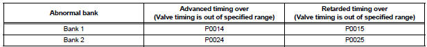
| P0014 P0024 |
Advanced cam timing:
With warm engine and engine speed of between 500
rpm and 4,000 rpm, all conditions (a), (b) and (c) are
met
(2 trip detection logic):
|
|
| P0015 P0025 |
Retarded cam timing:
With warm engine and engine speed of between 500
rpm and 4,000 rpm, all conditions (a), (b) and (c) are
met
(1 trip detection logic):
|
|
MONITOR DESCRIPTION
DTC P0014 and P0024
The ECM compares current valve timing with target valve timing, while the engine
is running and after
being warmed up, in order to monitor the VVT system on the exhaust side. Valve
timing is calculated from
the positions of the camshaft and crankshaft. The ECM controls the engine so
that current valve timing
meets target valve timing. If these timings are not met, the ECM determines this
as a malfunction.
DTC P0015 and P0025
The ECM compares current valve timing with target valve timing, while the engine
is running and after
being warmed up, in order to monitor the VVT system on the exhaust side. Valve
timing is calculated from
the positions of the camshaft and crankshaft. The ECM controls the engine so
that current valve timing
meets target valve timing. If these timings are not met, the ECM determines this
as a malfunction.
MONITOR STRATEGY
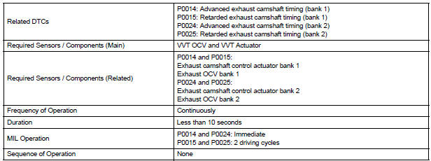
TYPICAL ENABLING CONDITIONS
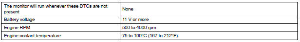
TYPICAL MALFUNCTION THRESHOLDS
Advanced camshaft timing:

Retarded camshaft timing:

If the difference between the target and actual camshaft timings is greater than the specified value, the ECM operates the VVT actuator.
Then, the ECM monitors the camshaft timing change for 5 seconds.
WIRING DIAGRAM
Refer to DTC P0013.
INSPECTION PROCEDURE
HINT:
- If DTC P0014 or P0015 is displayed, check the bank 1 VVT system circuit.
- Bank 1 refers to the bank that includes cylinder No. 1.
- If DTC P0024 or P0025 is displayed, check the bank 2 VVT system circuit.
- Bank 2 refers to the bank that does not include cylinder No. 1.
- Read freeze frame data using the intelligent tester. The ECM records vehicle and driving condition information as freeze frame data the moment a DTC is stored. When troubleshooting, freeze frame data can be helpful in determining whether the vehicle was running or stopped, whether the engine was warmed up or not, whether the air-fuel ratio was lean or rich, as well as other data recorded at the time of a malfunction.
1 CHECK ANY OTHER DTCS OUTPUT (IN ADDITION TO DTC P0014, P0015, P0024 OR P0025)
- Connect the intelligent tester to the DLC3.
- Turn the ignition switch to the ON position and turn the tester on.
- Select the following menu items: DIAGNOSIS / ENHANCED OBD II / DTC INFO / CURRENT CODES.
- Read the DTCs
Result

HINT: If any DTCs other than P0014, P0015, P0024 or P0025 are output, troubleshoot those DTCs first.
2 PERFORM ACTIVE TEST BY INTELLIGENT TESTER (OPERATE OCV)
- Connect the intelligent tester to the DLC3.
- Start the engine and turn the tester on.
- Warm up the engine.
- Select the following menu items on the tester: DIAGNOSIS / ENHANCED OBD II / ACTIVE TEST / VVT EX B1 or VVT EX B2.
- Check the engine speed while operating the Oil Control Valve (OCV) using the tester.
OK

3 CHECK WHETHER DTC OUTPUT RECURS (DTC P0014, P0015, P0024 OR P0025)
- Connect the intelligent tester to the DLC3.
- Turn the ignition switch to the ON position and turn the tester on.
- Clear the DTCs
- Start the engine and warm it up.
- Select the check mode using the tester.
- Drive the vehicle for more than 10 minutes.
- Read the DTCs using the tester.
OK: No DTC output
SYSTEM IS OK
4 CHECK VALVE TIMING (CHECK FOR LOOSE AND JUMP TEETH ON TIMING CHAIN)
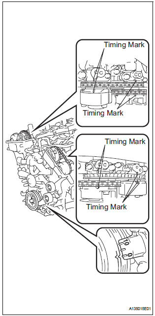
- Remove the cylinder head covers RH and LH.
- Turn the crankshaft to align the matchmarks of the crankshaft.
- Align the notch of the crankshaft pulley to the "0" position.
- Check if the matchmarks of the camshaft pulley and camshaft bearing cap align.
- Turn the crankshaft clockwise by 360 if the matchmarks do not align. Check if they align once again.
OK: The matchmarks of the camshaft pulley and the camshaft bearing cap align when the notch of the crankshaft pulley is in the "0" position.
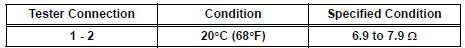
5 INSPECT CAMSHAFT TIMING OIL CONTROL VALVE ASSEMBLY (OCV)
- Remove the OCV.
- Measure the resistance according to the value(s) in the table below.
Standard resistance
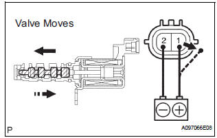
- Apply positive battery voltage to terminal 1 and negative
battery voltage to terminal 2. Check the valve operation.
OK: Valve moves quickly.
- Reinstall the OCV.
6 CHECK OIL PIPE AND OIL CONTROL VALVE FILTER
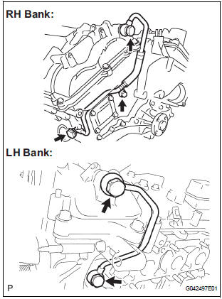
- Remove the oil pipe No. 1 or oil pipe assembly.
- Remove the oil control valve filter.
- Check that the filter and pipe are not clogged.
OK: The filter and pipe are not clogged
7 REPLACE CAMSHAFT TIMING GEAR ASSEMBLY
8 CHECK WHETHER DTC OUTPUT RECURS
- Connect the intelligent tester to the DLC3.
- Turn the ignition switch to the ON position and turn the tester on.
- Clear the DTCs.
- Start the engine and warm it up.
- Select the check mode using the tester.
- Drive the vehicle for more than 10 minutes.
- Confirm that no DTC is set using the tester.
OK: No DTC output.
HINT: DTC P0014, P0015, P0024 or P0025 is output when foreign objects in engine oil are caught in some parts of the system. These codes will stay registered even if the system returns to normal after a short time. These foreign objects are then captured by the oil filter, thus eliminating the source of the problem.
SYSTEM IS OK
 Camshaft Position "B" Actuator Circuit / Open
DTC P0013 Camshaft Position "B" Actuator Circuit / Open
(Bank 1)
DTC P0023 Camshaft Position "B" Actuator Circuit / Open
(Bank 2)
DESCRIPTION
The Variable Valve Timing (VVT) s ...
 Crankshaft Position - Camshaft Position Correlation
DTC P0016 Crankshaft Position - Camshaft Position Correlation
(Bank 1 Sensor A)
DTC P0017 Crankshaft Position - Camshaft Position Correlation
(Bank 1 Sensor B)
DTC P0018 Crankshaft Position - Cams ...
Other materials:
Noise Occurs
INSPECTION PROCEDURE
1 NOISE CONDITION
Check in which direction the noise comes from (front left
or right, or rear left or right).
Check in which direction the noise comes from.
OK:
The location of the noise source can be
determined
2 CHECK SPEAKERS
Check the installatio ...
Short in Front Pretensioner Squib LH Circuit
DTC B0135/73 Short in Front Pretensioner Squib LH Circuit
DESCRIPTION
The front pretensioner squib LH circuit consists of the center airbag sensor
assembly and the front seat
outer belt assembly LH.
This circuit instructs the SRS to deploy when deployment conditions are met.
DTC B0135/73 ...
VC Output Circuit
DESCRIPTION
The ECM constantly uses 5 V from the battery voltages supplied to the +B (BATT)
terminal to operate the
microprocessor. The ECM also provides this power to the sensors through the VC
output circuit.
When the VC circuit is short-circuited, the microprocessor in the ECM and
sens ...
