Toyota Sienna Service Manual: CAN Bus Line
DESCRIPTION
When any DTC for the CAN communication system is output, first measure the resistance between the terminals of the DLC3 to specify the trouble area, and check that there is no short in the CAN main wire, between the main wire, and +B or GND.
WIRING DIAGRAM
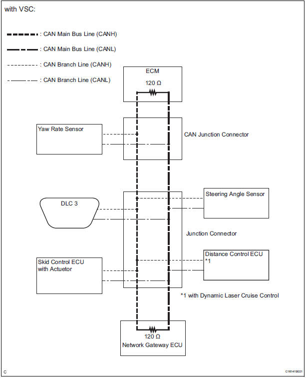
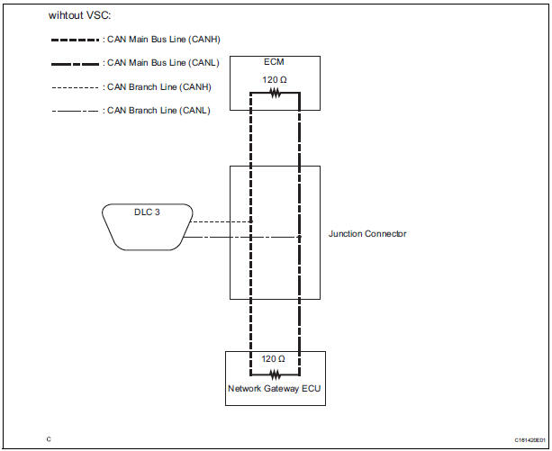
INSPECTION PROCEDURE
NOTICE:
- Turn the ignition switch off before measuring the resistances of CAN bus main wires and CAN bus branch wires.
- After the ignition switch is turned off, check that the key reminder warning system and light reminder warning system are not in operation.
- Before measuring the resistance, leave the vehicle as is for at least 1 minute and do not operate the ignition switch, any other switches, or the doors. If any doors need to be opened in order to check connectors, open the doors and leave them open.
HINT: Operating the ignition switch, any switches, or any doors triggers related ECU and sensor communication with the CAN. This communication will cause the resistance value to change.
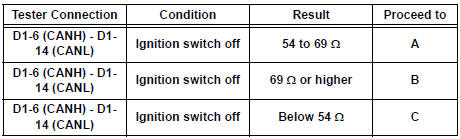
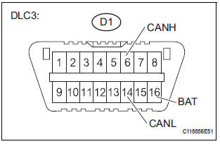
1 CHECK CAN BUS WIRE (MAIN WIRE FOR DISCONNECTION, CAN BUS LINES FOR SHORT CIRCUIT)
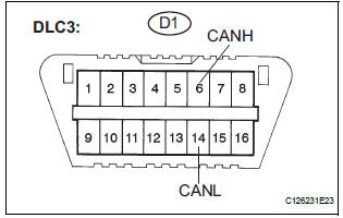
- Turn the ignition switch off.
- Measure the resistance according to the value(s) in the table below.
Standard resistance
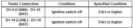
2 CHECK FOR SHORT TO B+ IN CAN BUS WIRE
- Measure the resistance according to the value(s) in the table below.
Standard resistance
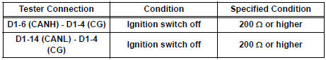
3 CHECK FOR SHORT TO GND IN CAN BUS WIRE
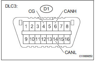
- Measure the resistance according to the value(s) in the table below.
Standard resistance
GO TO HOW TO PROCEED WITH TROUBLESHOOTING
 ECM Communication Stop Mode
DESCRIPTION
Detection Item
Symptom
Trouble Area
ECM Communication Stop
Mode
"Engine" is not displayed on the "Communication
Bus Che ...
 Open in CAN Main Bus Line
DESCRIPTION
There may be an open circuit in the CAN main bus wire and/or the DLC3 branch
wire when the resistance
between terminals 6 (CANH) and 14 (CANL) of the DLC3 is 69 Ω or higher.
...
Other materials:
Removal
1. REMOVE BACK DOOR CENTER GARNISH
Using a clip remover, disengage the 5 clips to
remove the back door center garnish.
2. REMOVE REAR SPOILER
Disconnect the center stop light connector.
Remove the 3 nuts.
Using a clip remover, disengage the 2 clips to
remove the rear s ...
Skid Control ECU Communication Stop Mode
DESCRIPTION
Detection Item
Symptom
Trouble Area
Skid Control ECU
Communication Stop
Mode
"ABS/VSC/TRC" is not displayed on the
"Communication Bus Check" screen of the
intelligent tester
Applies to "Skid Control ...
Installation
1. INSTALL IGNITION SWITCH ASSEMBLY
(a) Install the ignition switch with the 2 screws.
(b) Install the ignition switch connector.
2. INSTALL STEERING COLUMN COVER LOWER
(a) Attach the 4 claws to install the steering column
cover lower.
(b) Insert the key into the ignition key cylinde ...
