Toyota Sienna Service Manual: Check mode procedure
HINT:
Intelligent tester only: Compared to normal mode, check mode is more sensitive to malfunctions. Therefore, check mode can detect the malfunctions that cannot be detected by normal mode.
| NOTICE: All the stored DTCs and freeze frame data are erased if: 1) the ECM is changed from normal mode to check mode or vice versa; or 2) the ignition switch is turned off or turned to the ACC position from the ON position while in check mode. Before changing modes, always check and make a note of any DTCs and freeze frame data. |
1. CHECK MODE PROCEDURE (Using an intelligent tester)
(a) Check and ensure the following conditions:
(1) Battery voltage 12 V or more
(2) Throttle valve fully closed
(3) The shift lever in the P or N position
(4) A/C switched OFF
(b) Turn the ignition switch off.
(c) Connect an intelligent tester to the DLC3.
(d) Turn the ignition switch to the ON position.
(e) Turn the tester ON.
(f) Select the following menu items: DIAGNOSIS / ENHANCED OBD II / CHECK MODE.
(g) Switch the ECM from normal mode to check mode.
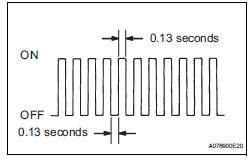
(h) Make sure that the MIL flashes as shown in the illustration.
(i) Start the engine.
(j) Make sure that the MIL goes off.
(k) Simulate the conditions of the malfunction described by the customer.
(l) Check for DTCs and freeze frame data using the tester.
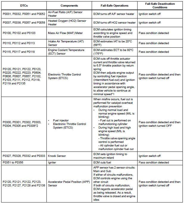
FAIL-SAFE CHART
If any of the following DTCs are set, the ECM enters fail-safe mode to allow the vehicle to be driven temporarily.
HINT:
- *1: The vehicle can be driven slowly when the accelerator pedal is depressed firmly and slowly. If the accelerator pedal is depressed quickly, the vehicle may speed up and slow down erratically.
- *2: Misfire related fail-safe operations occur when catalyst overheat malfunctions occur.
 Freeze frame data
1. DESCRIPTION
(a) The ECM records vehicle and driving condition
information as freeze frame data the moment a DTC
is stored. When troubleshooting, freeze frame data
can be helpful in determining ...

Other materials:
On-vehicle inspection
1. INSPECT OCCUPANT CLASSIFICATION ECU
(VEHICLE NOT INVOLVED IN COLLISION)
Perform a diagnostic system check.
2. INSPECT OCCUPANT CLASSIFICATION ECU
(VEHICLE INVOLVED IN COLLISION)
Perform a diagnostic system check.
Even if the airbag was not deployed, check if there
is ...
Park / Neutral Position Switch Circuit
DESCRIPTION
The clearance warning ECU receives the reverse or park position signal from
the park / neutral position
switch.
WIRING DIAGRAM
INSPECTION PROCEDURE
1 INSPECT CLEARANCE WARNING ECU
Disconnect the C9 connector from the clearance warning
ECU.
Measure the voltage ...
Distance Control ECU Power Source Circuit
DESCRIPTION
This circuit provides power to operate the distance control ECU. The distance
control ECU determines
information about the vehicle in front based on data from the laser sensor, and
then decides how much
acceleration and/or deceleration is needed to maintain the set distance. The
...
