Toyota Sienna Service Manual: Clearance warning ECU
COMPONENTS
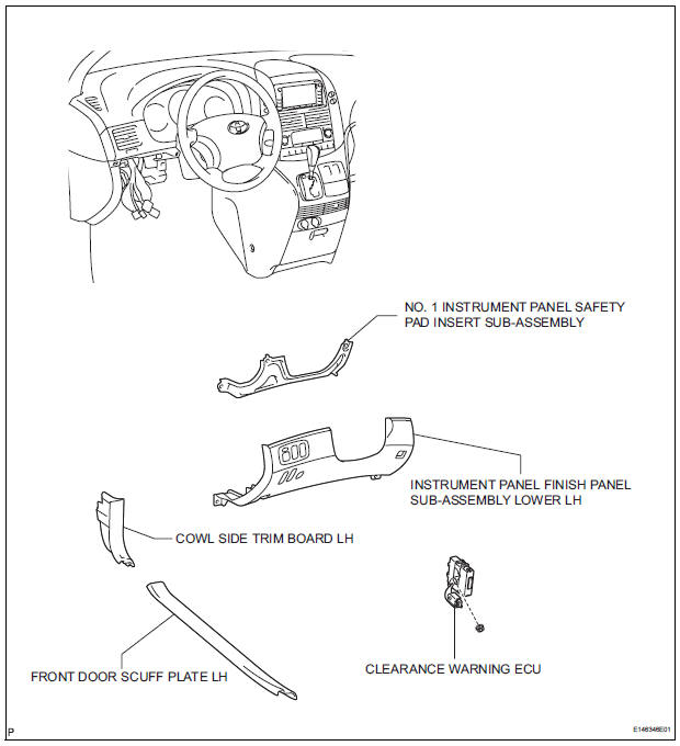
REMOVAL
1. REMOVE FRONT DOOR SCUFF PLATE LH
2. REMOVE COWL SIDE TRIM BOARD LH
3. REMOVE INSTRUMENT PANEL FINISH PANEL SUBASSEMBLY LOWER LH
4. REMOVE NO. 1 INSTRUMENT PANEL SAFETY PAD INSERT SUB-ASSEMBLY
5. REMOVE CLEARANCE WARNING ECU
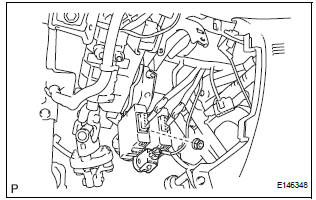
- Disconnect each connector.
- Remove the nut and clearance warning ECU.
INSTALLATION
1. INSTALL CLEARANCE WARNING ECU
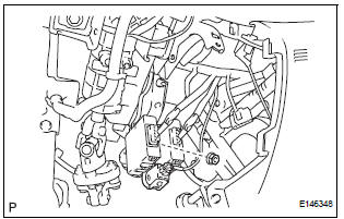
- Install the clearance warning ECU with the nut.
- Connect each connector.
2. INSTALL NO. 1 INSTRUMENT PANEL SAFETY PAD INSERT SUB-ASSEMBLY
3. INSTALL INSTRUMENT PANEL FINISH PANEL SUBASSEMBLY LOWER LH
4. INSTALL COWL SIDE TRIM BOARD LH
5. INSTALL FRONT DOOR SCUFF PLATE LH
 Display Signal Circuit between Radio and Navigation Assembly and
Television Camera Assembly
Display Signal Circuit between Radio and Navigation Assembly and
Television Camera Assembly
DESCRIPTION
This is the display signal circuit of the television camera assembly.
WIRING DIAGRAM
INSPECTION PROCEDURE
1 CHECK HARNESS AND CONNECTOR (RADIO AND NAVIGATION ASSEMBLY - TELEVISION ...
 No. 1 Ultrasonic sensor
COMPONENTS
REMOVAL
1. REMOVE FRONT FENDER LINER LH
2. REMOVE FRONT FENDER LINER RH
3. REMOVE FRONT BUMPER COVER
4. REMOVE REAR BUMPER COVER (2)
5. REMOVE NO. 1 ULTRASONIC SENSOR RETAINER
...
Other materials:
Torque Converter Clutch Solenoid Performance
(Shift Solenoid Valve DSL)
SYSTEM DESCRIPTION
The ECM uses the signals from the throttle position sensor, air-flow meter,
turbine (input) speed sensor,
intermediate (counter) shaft speed sensor and crankshaft position sensor to
monitor the engagement
condition of the lock-up clutch.
Then the ECM compares the eng ...
Brake Warning Light Remains ON
DESCRIPTION
If the ECU detects a trouble, it turns on the brake warning light at the same
time of prohibiting ABS
control.
At this time, the ECU records a DTC in memory.
Connect terminals TC and CG of the DLC3 to make the brake warning light blink
and output the DTC.
WIRING DIAGRAM
...
Radio Receiver Communication Error
INSPECTION PROCEDURE
1 IDENTIFY THE COMPONENT SHOWN BY THE SUB-CODE
Enter the diagnostic mode
Press the preset switch "3" to change to "Detailed
Information Mode".
Identify the component shown by the sub-code.
HINT:
"190 (radio receiver) ...
