Toyota Sienna Service Manual: Clearance Warning ECU Power Source Circuit
DESCRIPTION
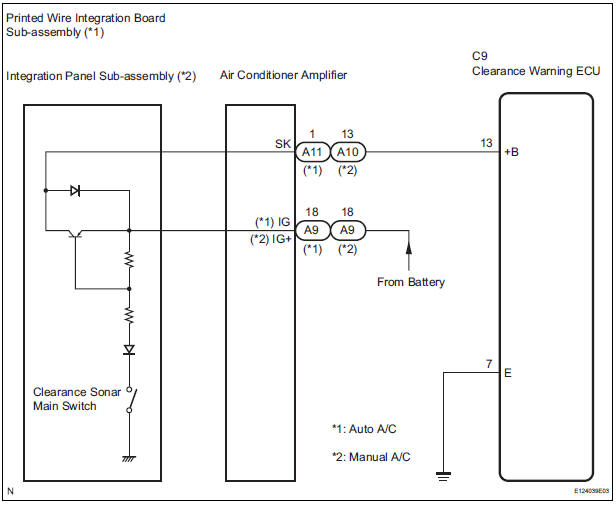
This circuit provides power to the clearance warning ECU.
WIRING DIAGRAM
INSPECTION PROCEDURE
1 CHECK HARNESS AND CONNECTOR (CLEARANCE WARNING ECU - AIR CONDITIONER AMPLIFIER)
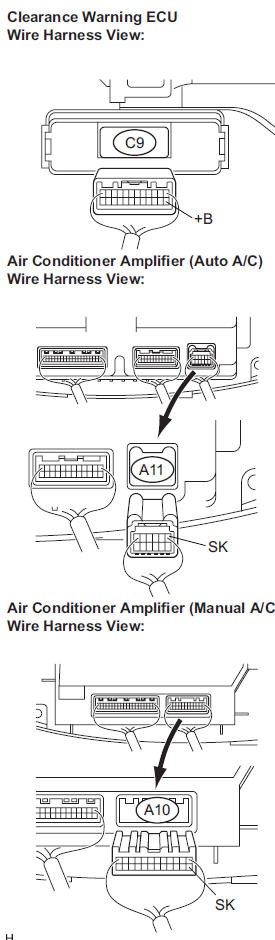
- Disconnect the connectors from the clearance warning ECU C9 and air conditioner amplifier connector A10 or A11.
- Measure the resistance according to the value(s) in the table below.
Standard resistance
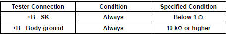
2 CHECK HARNESS AND CONNECTOR (CLEARANCE WARNING ECU - BODY GROUND)
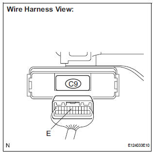
- Measure the resistance according to the value(s) in the table below.
Standard resistance
3 INSPECT CLEARANCE WARNING ECU
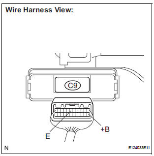
- Disconnect the clearance warning ECU connector.
- Turn the ignition switch ON.
- Turn the clearance sonar main switch ON.
- Measure the voltage between terminals +B and E of the ECU.
Standard voltage: 10 to 14 V
Result
PROCEED TO NEXT CIRCUIT INSPECTION SHOWN IN PROBLEM SYMPTOMS TABLE
4 INSPECT PRINTED WIRE INTEGRATION BOARD SUB-ASSEMBLY
- Check that the malfunction disappears when a known good printed wire integration board sub-assembly is installed.
OK: Malfunction disappears
REPLACE PRINTED WIRE INTEGRATION BOARD SUB-ASSEMBLY
5 INSPECT INTEGRATION PANEL SUB-ASSEMBLY
- Check that the malfunction disappears when a known good integration panel sub-assembly is installed.
OK: Malfunction disappears.
REPLACE INTEGRATION PANEL SUB-ASSEMBLY
 No. 1 Clearance Warning Buzzer Circuit
DESCRIPTION
The clearance warning ECU receives the ultrasonic sensor signal to sound the
front warning buzzer.
WIRING DIAGRAM
INSPECTION PROCEDURE
1 INSPECT FRONT BUZZER
Remove the c ...
 No. 2 Clearance Warning Buzzer Circuit
DESCRIPTION
The clearance warning ECU receives the ultrasonic sensor signal to sound the
rear warning buzzer.
WIRING DIAGRAM
INSPECTION PROCEDURE
1 CHECK HARNESS AND CONNECTOR (CLEARANCE WAR ...
Other materials:
Typical tire symbols
Run-flat tire or full-size tire
Compact spare tire
Tire size
DOT and Tire Identification Number (TIN)
Uniform tire quality grading
For details, see “Uniform Tire Quality Grading” that follows.
Location of treadwear indicators
Run-flat tire (RFT) or standard ti ...
Adjustment procedure
Manual seat
Seat position adjustment lever
Seatback angle adjustment lever
Vertical height adjustment lever (driver’s side only)
Lumbar support adjustment switch (driver’s side only)*
*: If equipped
Power seat
Seat position adjustment switch
Seatback angle a ...
Mass or Volume Air Flow Circuit Range / Performance
Problem
DTC P0101 Mass or Volume Air Flow Circuit Range / Performance
Problem
DESCRIPTION
Refer to DTC P0100
DTC No.
DTC Detection Condition
Trouble Area
P0101
High voltage:
Conditions (a), (b) and (c) continue for more than
10 seconds (2 trip de ...
