Toyota Sienna Service Manual: Control Module Performance

DESCRIPTION
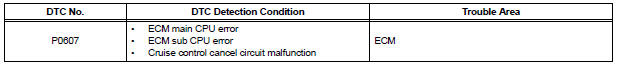
The ECM continuously monitors its main and sub CPUs. This self-check ensures that the ECM is functioning properly. If outputs from the CPUs are different and deviate from the standards, the ECM will illuminate the MIL and set a DTC immediately.
The ECM also monitors the cruise control cancel circuit. If this circuit malfunctions, the ECM will set a DTC immediately (MIL is not illuminated).
| NOTICE: First check for an exhaust gas leak around the HO2S if P0606 is present. An exhaust gas leak generates noise in the HO2S output. The ECM may interpret this as an HO2S transistor malfunction. |
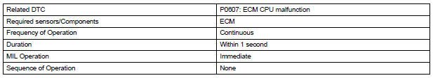
MONITOR STRATEGY
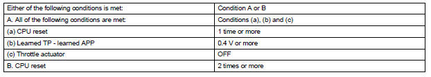
TYPICAL ENABLING CONDITIONS

TYPICAL MALFUNCTION THRESHOLDS
INSPECTION PROCEDURE
1 CHECK WHETHER DTC OUTPUT RECURS (IN ADDITION TO DTC P0607)
(a) Connect the intelligent tester to the DLC3.
(b) Turn the ignition switch to the ON position.
(c) Turn the tester on.
(d) Clear the DTC.
(e) Turn the ignition switch off.
(f) Disconnect the battery negative terminal and wait for 1 minute.
(g) Connect the battery negative terminal.
(h) Turn the ignition switch to the ON position.
(i) Enter the following menus: DIAGNOSIS / ENHANCED II / DTC INFO / CURRENT CODES.
(j) Read the DTCs.
Result 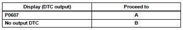

REPLACE ECM
 ECM / PCM Processor
DESCRIPTION
The ECM continuously monitors its internal processors (CPUs), A/F sensor
transistors and heated oxygen
sensor (HO2S) transistors. This self-check ensures that the ECM is functionin ...
 Starter Relay Circuit High
MONITOR DESCRIPTION
While the engine is being cranked, the positive battery voltage is applied to
terminal STA of the ECM.
If the ECM detects the Starter Control (STA) signal while the vehic ...
Other materials:
Reassembly
1. INSTALL NO. 1 SEAT CUSHION FRAME SUBASSEMBLY
Install the seat cushion frame with the bolt.
Torque: 20.6 N*m (210 kgf*cm, 15 ft.*lbf)
2. INSTALL RECLINING CONTROL LINK SUBASSEMBLY
Install the reclining control link with the E-ring.
Install the nut.
3. INSTALL RE ...
Inspection and adjustment procedure
Tire valve
Tire pressure gauge
Remove the tire valve cap.
Press the tip of the tire pressure gauge onto the tire valve.
Read the pressure using the gauge gradations.
If the tire inflation pressure is not at the recommended level, adjust
the pressure.
If you add too much air, ...
Types of child restraints
Child restraint systems are classified into the following 3 types
according to the age and size of the child:
Rear facing - Infant seat/convertible seat
Forward facing - Convertible seat
Booster seat
Selecting an appropriate child restraint system
Use a child rest ...
