Toyota Sienna Service Manual: Cooling fan ecu
ON-VEHICLE INSPECTION
1. INSPECT COOLING FAN ECU
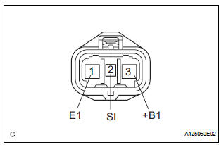
(a) Inspect the input voltage.
(1) Disconnect the cooling fan ECU connector.
(2) Turn the ignition switch to the ON position.
Check the voltage of the +B terminal of the disconnected wire harness side connector.
Standard voltage: 9 to 14 V
If the result is not as specified, inspect the power source system (fusible link, fuse, wire harness and relay).
(b) Inspect the cooling fan motor (See page CO-19).
(c) Measure the resistance between terminals RFC (ECM) and SI (cooling fan ECU) of the wire harness side connectors.V
HINT:
- If the fan does not operate, there may be a short circuit.
- If the fan remains operating, there may be an open circuit.
(d) Inspect the ECM power source circuit and ground circuit.
 Cooling fan motor
On-vehicle inspection
1. No. 1 Cooling fan motor
(A) check that the motor turns smoothly when the
battery is connected to the fan motor connector.
(B) measure the current while the motor is ...
 Cooling fan relay
On-vehicle inspection
1. Cooling fan relay
(a) Remove the relay from engine room relay block No.
1.
(b) Measure the resistance of the relay.
Standard resistance
If the result is not as ...
Other materials:
Installation
1. INSTALL REAR SEAT 3 POINT TYPE BELT
ASSEMBLY (for 8-Passenger)
HINT: Refer to the instructions for reassembly of the rear
No. 1 seat assembly (for center seat).
Install the rear seat 3 point type belt assembly with
the bolt.
Torque: 42 N*m (430 kgf*cm, 31 ft.*lbf)
2. INSTALL ...
Screen for general settings
Press the “SETUP” button.
Select “General” on the “Setup”
screen.
Select to adjust the clock.
“English”, “Français” or
“Español” can be selected.
On/off can be selected to
sound beeps.
Select to change the screen
color.
Select ...
Problem symptoms table
POWER SLIDE DOOR SYSTEM
Symptom
Suspected Area
Power slide door LH does not operate when switch* is
pressed (* switch indicates satellite switch for power
slide door LH and power slide door control switch LH)
ECU-B fuse
Power slide door main switch ...
