Toyota Sienna Service Manual: Cruise Control Switch Circuit
DESCRIPTION
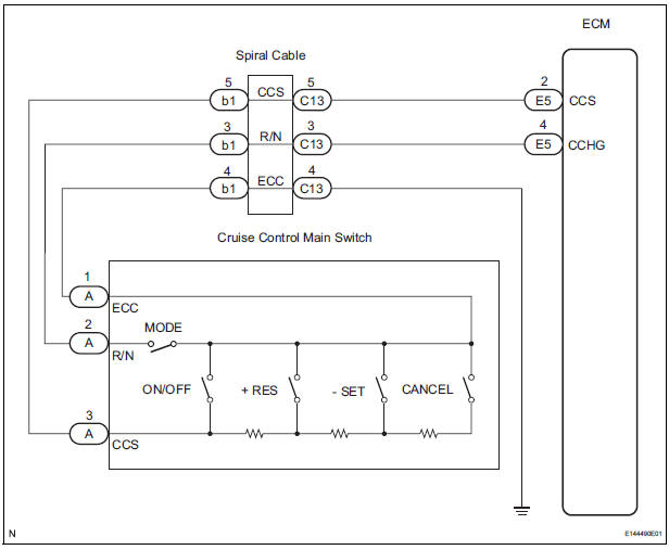
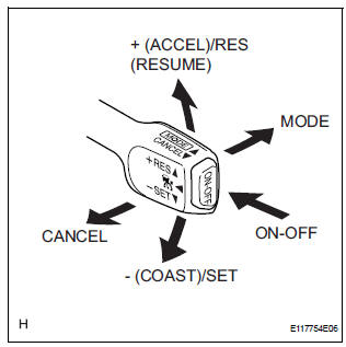
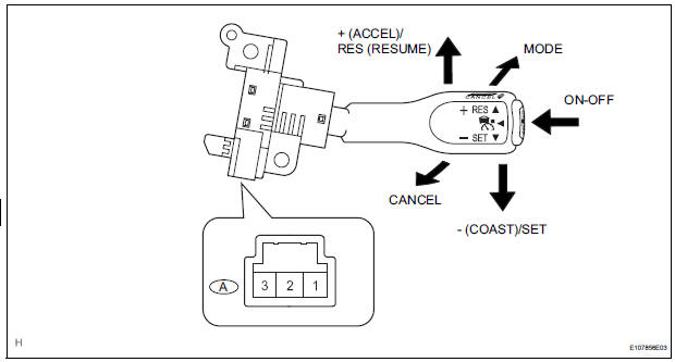
The cruise control main switch operates 8 functions: SET, - (COAST), TAP-DOWN, RES (RESUME), + (ACCEL), TAP-UP, CANCEL, and MODE. The SET, TAP-DOWN, and - (COAST) functions, and the RES (RESUME), TAP-UP, and + (ACCEL) functions are operated with the same switch. The cruise control main switch is an automatic return type switch which turns on only while operating it in the direction of each arrow and turns off after releasing it. The internal contact point of the cruise control main switch is turned on with the switch operation. The ECM then reads the voltage value that has been changed by the switch operation to control MODE, SET, - (COAST), RES (RESUME), + (ACCEL), and CANCEL. The dynamic laser cruise control system has two cruise control modes: the constant speed control mode and vehicle-to-vehicle distance control mode.
- The vehicle-to-vehicle distance control mode is always selected when starting up the dynamic laser cruise control system.
- The operation of the constant speed control mode is the same as that for a conventional cruise control system.
WIRING DIAGRAM
INSPECTION PROCEDURE
1 READ VALUE OF INTELLIGENT TESTER
- Connect the intelligent tester to the DLC3.
- Turn the ignition switch to the ON position and turn the intelligent tester main switch on.
- Check the DATA LIST for proper functioning of the cruise control main switch.
ECM (Cruise control):
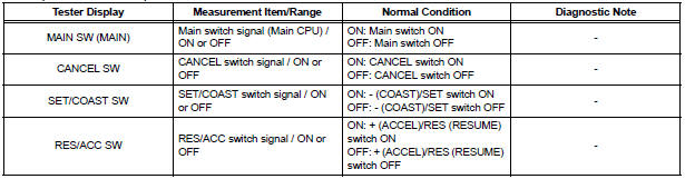
OK: When the cruise control main switch is operated, the display changes as shown above.
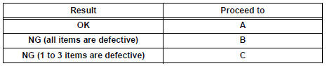
Result
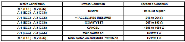
2 INSPECT CRUISE CONTROL MAIN SWITCH
- Remove the cruise control main switch
- Measure the resistance according to the value(s) in the table below
Standard resistance
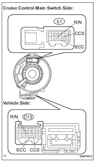
3 INSPECT HARNESS AND CONNECTOR (CRUISE CONTROL MAIN SWITCH - SPIRAL CABLE)
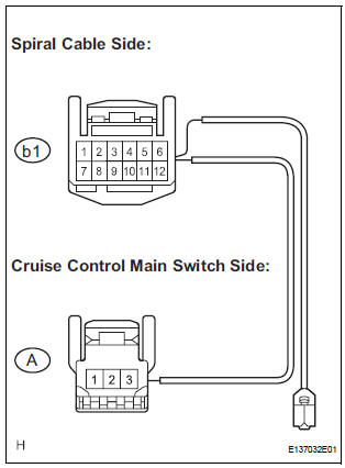
- Disconnect the b1 connector from the spiral cable.
- Measure the resistance according to the value(s) in the table below.
Standard resistance
4 INSPECT SPIRAL CABLE
NOTICE: The spiral cable is an important part of the SRS airbag system. Incorrect removal or installation of the spiral cable may prevent the airbag from deploying. Be sure to read the page shown in the brackets.
HINT:
- Removal (34)
- Installation
- Remove the spiral cable.
- Measure the resistance according to the value(s) in the table below.
Standard resistance
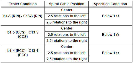
HINT: The spiral cable makes a maximum of approximately 5 rotations
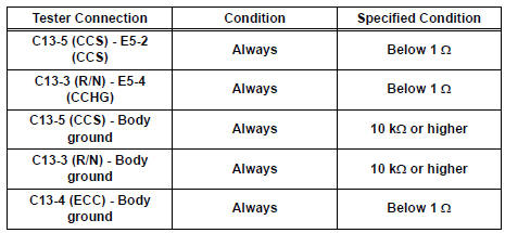
5 CHECK HARNESS AND CONNECTOR (SPIRAL CABLE - ECM)
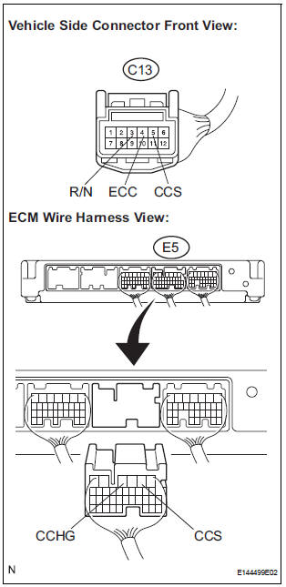
- Measure the resistance according to the value(s) in the table below.
Standard resistance
REPLACE ECM
 Lost Communication with Radar Sensor
DTC U1102 Lost Communication with Radar Sensor
DESCRIPTION
The laser sensor and distance control ECU transmit the data for general
vehicle control and diagnosis
function along the communication l ...
 Distance Control ECU Power Source Circuit
DESCRIPTION
This circuit provides power to operate the distance control ECU. The distance
control ECU determines
information about the vehicle in front based on data from the laser sensor, and
t ...
Other materials:
Short to B+ in Driver Side Squib 2nd Step Circuit
DTC B1183/22 Short to B+ in Driver Side Squib 2nd Step Circuit
DESCRIPTION
The driver side squib 2nd step circuit consists of the center airbag sensor
assembly, the spiral cable and
the steering pad.
The circuit instructs the SRS to deploy when deployment conditions are met.
DTC B1183/22 ...
Locking the front doors from the outside without a key
Move the inside lock button to the lock position.
Close the door.
Vehicles without a smart key system
The doors cannot be locked if either of the front doors is open and the
key is in the engine switch.
Vehicles with a smart key system
The door cannot be locked if the engine switc ...
DTC check / clear
1. CHECK DTC (USING INTELLIGENT TESTER)
Checking DTCs.
Connect the intelligent tester to the DLC3.
Turn the ignition switch ON.
Read DTCs by following the prompts on the
tester screen.
HINT:
Refer to the intelligent tester operator's manual
for further details.
2. CLEAR DTC ...
