Toyota Sienna Service Manual: Data list / active test
1. DATA LIST
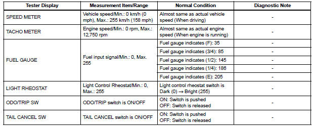
Using the intelligent tester to read the Data List allows the values or states of switches, sensors, actuators and other items to be read without removing any parts. This non-intrusive inspection can be very useful because intermittent conditions or signals may be discovered before parts or wiring is disturbed. Reading the Data List information early in troubleshooting is one way to save diagnostic time.
- Warm up the engine.
- Turn the ignition switch off.
- Connect the intelligent tester to the DLC3.
- Turn the ignition switch to the ON position.
- Turn the tester ON.
- Enter following menus: DIAGNOSIS / OBD/MOBD / METER / DATA LIST.
METER:
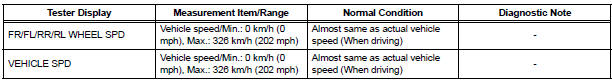
ABS/TRAC/VSC:
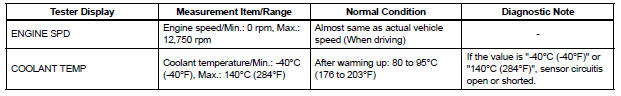
ENGINE:
2. ACTIVE TEST
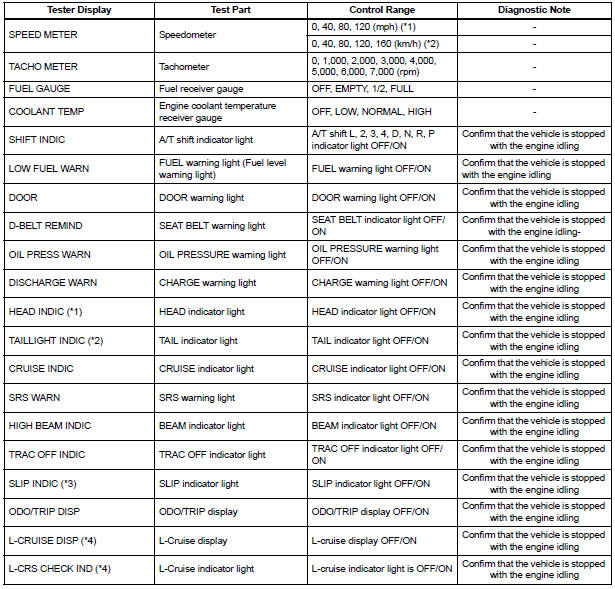
Using the intelligent tester to perform Active Tests allows relays, VSVs, actuators and other items to be operated without removing any parts. This non-intrusive functional inspection can be very useful because intermittent operation may be discovered before parts or wiring is disturbed. Performing Active Tests early in troubleshooting is one way to save diagnostic time.
Data List information can be displayed while performing Active Tests.
- Connect the intelligent tester to the DLC3.
- Turn the ignition switch to the ON position.
- Turn the tester ON.
- Enter following menus: DIAGNOSIS / OBD/MOBD / METER / ACTIVE TEST
METER:
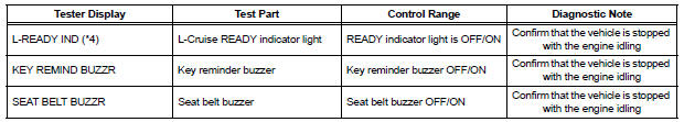
MAIN BODY:

*1: for U.S.A.
*2: Except for U.S.A.
*3: with VSC
*4: with Dynamic Laser Cruise Control System
*5: for Optitron Meter
 Diagnosis system
1. CHECK DLC3
The ECU uses the ISO 15765-4 for communication
protocol. The terminal arrangement of the DLC3
complies with SAE J1962 and matches the ISO
15765-4 format.
NOTICE:
...
 On-vehicle inspection
1. INSPECT SPEEDOMETER
Check the operation.
Using a speedometer tester, check the
speedometer indication according to the table
below.
Reference: mph (U.S.A.)
Referen ...
Other materials:
Cranking Holding Function Circuit
DESCRIPTION
The system detects the ignition switch's starting signal (STSW) and then
supplies current to the starter
until the ECM judges that the engine has started successfully. The purpose is to
reduce the holding time
of the ignition key.
WIRING DIAGRAM
Refer to DTC P0617.
INSPECTI ...
Replacement
1. DISCHARGE REFRIGERANT FROM
REFRIGERATION SYSTEM
SST 07110-58060 (07117-58080, 07117-58090,
07117-78050, 07117-88060, 07117-88070,
07117-88080)
(a) Turn the A/C switch to ON.
(b) Operating the cooler compressor at the engine rpm
of approx. 1,000 for 5 to 6 minutes, circulate the
refriger ...
Vehicle interior
Items
Check points
Accelerator pedal
The accelerator pedal should move
smoothly (without uneven pedal effort or
catching).
Automatic transaxle “Park”
mechanism
When parked on a slope with the shift
lever in P, is ...
