Toyota Sienna Service Manual: Diagnosis Circuit
DESCRIPTION
DTC output mode is set by connecting terminals TC and CG of the DLC3.
DTCs are displayed by blinking the SRS warning light.
HINT:
- When each warning light stays blinking, a ground short in the wiring of terminal TC of the DLC3 or an internal ground short in each ECU is suspected.
- A DTC output mode signal is transmitted through BEAN and CAN to each ECU including the center airbag sensor assembly. Thus when all systems do not enter DTC output mode, there may be an ECM malfunction
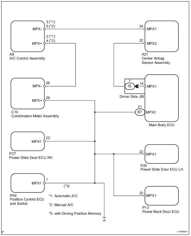
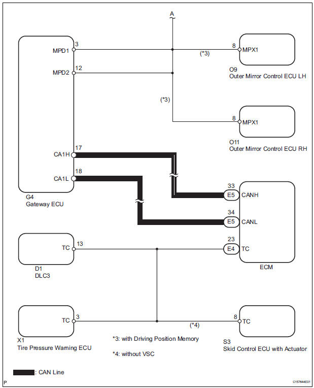
WIRING DIAGRAM
INSPECTION PROCEDURE
1 CHECK MULTIPLEX COMMUNICATION SYSTEM
- Check if the multiplex communication system DTC is output.
HINT: The center airbag sensor assembly of this system is connected to the multiplex communication system.
Therefore, before starting troubleshooting, make sure to check that there is no trouble in the multiplex communication system.
OK: The Multiplex communication system DTC is not output.
 REPAIR CIRCUITS INDICATED BY
OUTPUT
DTCS
REPAIR CIRCUITS INDICATED BY
OUTPUT
DTCS

2 CHECK CAN COMMUNICATION SYSTEM
- Use the intelligent tester to check if the CAN communication system is functioning normally.
HINT: The ECM is connected to the CAN communication system. Therefore, before starting troubleshooting, make sure to check that there is no trouble in the CAN communication system.
OK: The CAN communication system is functioning normally.
 REPAIR CAN COMMUNICATION
CIRCUIT
REPAIR CAN COMMUNICATION
CIRCUIT

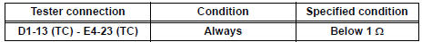
3 CHECK WIRE HARNESS (TC OF DLC3 - TC OF ECM)
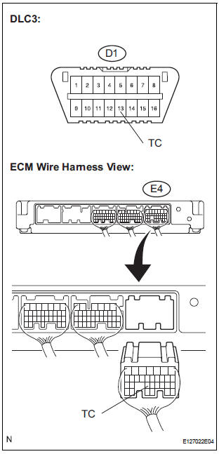
- Turn the ignition switch to the LOCK position.
- Disconnect the connector from the ECM.
- Measure the resistance according to the value(s) in the table below.
Standard resistance
 REPAIR OR REPLACE WIRE
HARNESS (TC
OF DLC3 - TC OF ECM)
REPAIR OR REPLACE WIRE
HARNESS (TC
OF DLC3 - TC OF ECM)

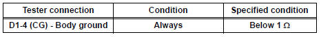
4 CHECK WIRE HARNESS (CG OF DLC3 - BODY GROUND)
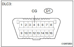
- Measure the resistance according to the value(s) in the table below.
Standard resistance
 REPAIR OR REPLACE WIRE
HARNESS (CG
OF DLC3 - BODY GROUND)
REPAIR OR REPLACE WIRE
HARNESS (CG
OF DLC3 - BODY GROUND)

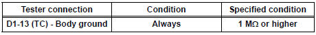
5 CHECK WIRE HARNESS (TC OF DLC3 - BODY GROUND)
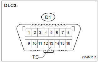
- Measure the resistance according to the value(s) in the table below.
Standard resistance
 REPAIR OR REPLACE WIRE
HARNESS OR
EACH ECU
REPAIR OR REPLACE WIRE
HARNESS OR
EACH ECU

REPLACE CENTER AIRBAG SENSOR ASSEMBLY
 SRS Warning Light does not Come ON
DESCRIPTION
WIRING DIAGRAM
INSPECTION PROCEDURE
1 CHECK BATTERY
Measure the voltage of the battery.
Standard voltage:
11 to 14 V
CHECK AND REPLACE BATTERY OR
CHARGING SYSTEM
2 CHECK CO ...

Other materials:
Reassembly
1. INSTALL INPUT SHAFT OIL SEAL RING
(a) Compress a new input shaft oil seal ring from both
sides to reduce dimension A.
Dimension A:
5 mm (0.197 in.)
(b) Coat the oil seal ring with ATF and install it to the
input shaft.
NOTICE:
Do not expand the end gap of the oil seal ring
too much. ...
Receiving a message
When an e-mail/SMS/MMS is received, the incoming message screen
pops up with sound and is ready to be operated on the screen.
Select to check the message.
Select to refuse the message.
Select to call the message
sender.
Receiving a message
Depending on the cellular phone used f ...
Installation
1. INSTALL NO. 1 REAR DIFFERENTIAL SUPPORT
(a) Install the No. 1 rear differential support to the rear
differential carrier assembly with the 2 bolts and 2
nuts.
Torque: 85 N*m (867 kgf*cm, 63 ft.*lbf)
HINT:
Hold the bolt and tighten the nut.
2. INSTALL REAR DIFFERENTIAL DYNAMIC DAMPER
...
