Toyota Sienna Service Manual: Diagnosis system
1. CHECK BATTERY VOLTAGE
Standard voltage: 11 to 14 V
If the voltage is below 11 V, recharge the battery before proceeding.
2. CHECK DLC3
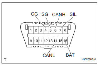
(a) The ECU uses the ISO 15765-4 for communication protocol. The terminal arrangement of the DLC3 complies with SAE J1962 and matches the ISO 15765-4 format.
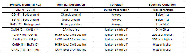
NOTICE: *: Before measuring the resistance, leave the vehicle as is for at least 1 minute and do not operate the ignition switch, any other switches or the doors.
(b) If the result is not as specified, DLC3 may have a malfunction. Repair or replace the harness and connector.
HINT: Connect the cable of the intelligent tester to DLC3, turn the ignition switch to the ON position and attempt to use the tester. If the display indicates that a communication error has occurred, there is a problem either with the vehicle or with the tester.
- If communication is normal when the tester is connected to another vehicle, inspect DLC3 of the original vehicle.
- If communication is still not possible when the tester is connected to another vehicle, the problem may be in the tester itself. Consult the Service Department listed in the tester's instruction manual.
3. DIAGNOSIS SYSTEM
(a) DTCs (Normal mode) (1) DTCs are memorized in the tire pressure warning ECU and read by the blinks of the tire pressure warning light or by using the intelligent tester (See page TW-34).
(b) Test mode
(1) By switching from normal mode into test mode (input signal check), you can inspect the tire pressure warning antenna and receiver, each tire pressure warning valve and transmitter, and vehicle speed sensor (See page TW-25).
(c) When there is a problem with the tire pressure warning system, the tire pressure warning light blinks at 0.5-second intervals, and turns on after 1 minute.
4. CHECK TIRE PRESSURE WARNING LIGHT
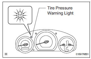
(a) Turn the ignition switch to the ON position.
(b) Check that the tire pressure warning light comes on for 3 seconds.
If the warning check result is not normal, proceed to
the troubleshooting for the tire pressure warning
light circuit.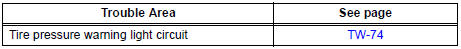
5. TIRE PRESSURE WARNING LIGHT AND INDICATOR CHART
HINT: The table below indicates the state of the tire pressure warning light and indicator after the ignition switch ON.
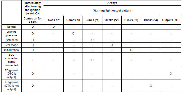
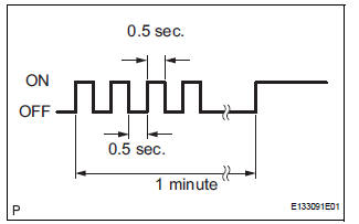
*1: Comes on and goes off repeatedly at 0.5-second intervals, and comes on after 1 minute.
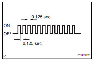
*2: Comes on and goes off repeatedly at 0.125-second intervals.
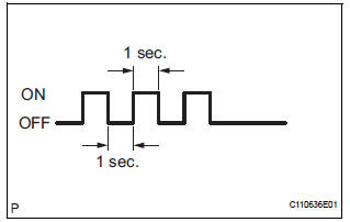
*3: Blinks 3 times (1 second on, 1 second off).
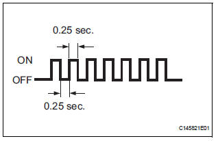
*4: Comes on and goes off repeatedly at 0.25-second intervals.
 Terminals of ecu
Check tire pressure warning ecu
HINT:
Inspect the connectors from the back side while the
connectors are connected.
(a) Disconnect the tire pressure warning antenna and
receiver connector.
...
 Dtc check / clear
1. DTC CHECK (USING SST CHECK WIRE)
(a) Check DTCs.
(1) Turn the ignition switch off.
(2) Using SST, connect terminals TC and CG of
DLC3.
SST 09843-18040
(3) Turn the ignition switch to ...
Other materials:
Freeze frame data
1. DESCRIPTION
The ECM records vehicle and driving condition
information as freeze frame data the moment a DTC
is stored. When troubleshooting, freeze frame data
can be helpful in determining whether the vehicle
was running or stopped, whether the engine was
warmed up or not, whe ...
Inspection
1. INSPECT BRAKE CYLINDER AND PISTON
(a) Check the brake cylinder bore and rear disc brake
piston for rust or scoring.
2. INSPECT PAD LINING THICKNESS
(a) Using a ruler, measure the pad lining thickness.
Standard thickness:
11.0mm (0.433 in.)
Minimum thickness:
1.0 mm (0.039 in.)
3. INS ...
Removal
1. DISCHARGE FUEL SYSTEM PRESSURE
HINT:
See page FU-1.
2. DISCONNECT CABLE FROM NEGATIVE BATTERY
TERMINAL
3. REMOVE NO. 1 ENGINE UNDER COVER
4. DRAIN ENGINE COOLANT (See page CO-6)
5. REMOVE FRONT WIPER ARM HEAD CAP (See page
WW-4)
6. REMOVE FRONT WIPER ARM RH (See page WW-4)
7. REMOVE FRO ...
