Toyota Sienna Service Manual: Disassembly
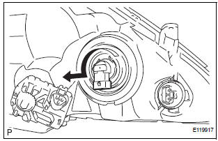
1. REMOVE NO. 1 HEADLIGHT BULB (HALOGEN HEADLIGHT)
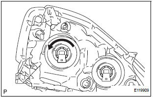
- Turn in the direction indicated by the arrow and remove the No. 1 headlight bulb.
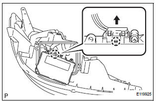
2. REMOVE DISCHARGE HEADLIGHT BULB (DISCHARGE HEADLIGHT)
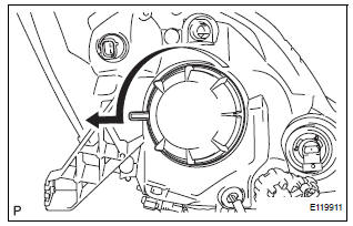
- Turn in the direction indicated by the arrow and disconnect the socket.
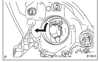
- Release the lock of the set spring and remove the discharge headlight bulb as shown in the illustration.
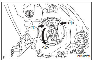
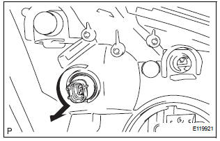
3. REMOVE NO. 2 HEADLIGHT BULB
- Turn in the direction indicated by the arrow and remove the No. 2 headlight bulb.
4. REMOVE FRONT TURN SIGNAL LIGHT BULB
- Turn in the direction indicated by the arrow and remove the front turn signal light bulb and front turn signal light socket as a unit.
- Remove the front turn signal light bulb from the front turn signal light socket.
5. REMOVE FRONT SIDE MARKER LIGHT BULB
- Turn in the direction indicated by the arrow and remove the side marker light bulb and side marker light socket as a unit.
- Remove the side marker light bulb from the side marker light socket.
6. REMOVE LIGHT CONTROL ECU (DISCHARGE HEADLIGHT)
- Remove the 4 screws and headlight cover.
- Remove the headlight gasket.
- Remove the 2 screws.
- Disengage the claw.
- Disconnect the connector and remove the light control ECU.
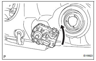
- Remove the headlight leveling motor assembly as shown in the illustration.
- Remove the headlight leveling motor base packing.
 Removal
1. DISCONNECT CABLE FROM NEGATIVE BATTERY
TERMINAL
2. REMOVE FRONT BUMPER ASSEMBLY
3. REMOVE HEADLIGHT ASSEMBLY
Disconnect the connectors.
Remove the bolt, 3 screws and headligh ...
 Adjustment
1. VEHICLE PREPARATION FOR HEADLIGHT AIMING
ADJUSTMENT
Prepare the vehicle:
Ensure there is no damage or deformation to the
body around the headlights.
Fill the fuel t ...
Other materials:
If the engine will not
start
If the engine will not start even though correct starting procedures
are being followed (, 228), consider each of the following
points:
The engine will not start even though the starter motor operates
normally.
One of the following may be the cause of the problem:
There may not be sufficien ...
Problem symptoms table
RESULT LIST OF CHECK CAN BUS LINE
Symptom
Suspected Area
All ECUs and sensors connected to the CAN
communication system are not displayed on intelligent
tester
CAN Bus Line
The result of "CAN BUS WIRE CHECK" is "Open in
CAN Main Bus Lin ...
Meter Illumination is Always Dark
DESCRIPTION
Confirm that the vehicle is equipped with the optitron meter, then
check this circuit.
The combination meter assembly receives a auto dimmer signal from the
body ECU by the multiplex
communication line.
WIRING DIAGRAM
INSPECTION PROCEDURE
1 CHECK MULTIPLEX CO ...
