Toyota Sienna Service Manual: Disassembly
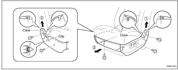
1. REMOVE FRONT SEAT SIDE TABLE LEG COVER (w/ Table)
- Using a screwdriver, disengage the claws and remove the seat side table leg cover.
HINT: Tape the screwdriver tip before use.
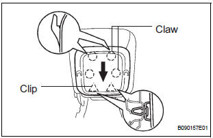
2. REMOVE FRONT SEAT SIDE TABLE (w/ Table)
- Remove the 4 nuts and seat side table.
- Remove the 2 clips and seat side table cover.
3. REMOVE OCCUPANT CLASSIFICATION ECU (for Front Passenger Seat)
4. REMOVE RECLINING POWER SEAT SWITCH KNOB
- Using a screwdriver, remove the reclining power seat switch knob.
HINT: Tape up the screwdriver tip before.
5. REMOVE SLIDE & VERTICAL POWER SEAT SWITCH KNOB
- Using a screwdriver, remove the slide & vertical power seat switch knob.
HINT: Tape up the screwdriver tip before.
6. REMOVE FRONT SEAT CUSHION SHIELD INNER LH
- Remove the 7 screws.
- Using a screwdriver, disengage the 4 claws and clip, and remove the front seat cushion shield LH together with the front seat cushion shield inner LH and front seat cushion shield inner No. 1 LH.
HINT: Tape the screwdriver tip before use.
- Remove the screw and front seat cushion shield
inner LH from the front seat cushion shield inner No.
1 LH.
7. REMOVE NO. 1 FRONT SEAT CUSHION SHIELD INNER LH
- Remove the screw and front seat cushion shield inner No. 1 LH from the front seat cushion shield LH.
8. REMOVE POWER SEAT SWITCH (for Driver Seat)
- Remove the 2 screws and the power seat switch.
9. REMOVE FRONT POWER SEAT SWITCH LH
- Disconnect the connector.
- Remove the 3 screws and power seat switch LH.
10. REMOVE FRONT SEAT INNER BELT ASSEMBLY LH
- Disconnect the connectors.
- Remove the nut and inner belt assembly.
11. REMOVE FRONT SEAT TRACK COVER LH FRONT OUTER
- Remove the clip, 2 screws and seat track cover front outer.
12. REMOVE FRONT SEAT TRACK COVER LH FRONT INNER
- Remove the clip, 2 screws and seat track cover front inner.
13. REMOVE FRONT SEAT INNER LH ARMREST ASSEMBLY
- Using a screwdriver, pry out the armrest cap.
HINT: Tape the screwdriver tip before use.
- Remove the bolt and armrest assembly.
- Remove the 2 washers and 2 spacers.
14. REMOVE SEAT CUSHION COVER WITH PAD
- with Seat heater: Disconnect the connector.
- Disengage the clamps and hooks.
- Disengage the hooks and remove the seat cushion cover with pad.
15. REMOVE SEPARATE TYPE FRONT SEAT CUSHION COVER
- Remove the hog rings and the separate type front seat cushion cover.
16. REMOVE FRONT SEAT CUSHION HEATER ASSEMBLY LH (w/ Seat Heater System)
- Cut off the tack pins which fasten the seat heater and then remove the front seat heater from the cushion cover.
NOTICE: Be careful not to damage the seat cushion cover.
17. REMOVE FRONT SEATBACK BOARD LH
- Disengage the clips.
- Remove the seatback board by pulling it out in the arrow mark direction shown in the illustration.
18. REMOVE FRONT SEAT HEADREST SUPPORT
- Disengage the claw and remove the 2 headrest supports.
19. REMOVE SEATBACK COVER WITH PAD
- with Side airbag: Remove the nut and disengage the separate type front seatback cover bracket.
- Remove the hog rings and disengage the hooks.
- Remove the seatback cover with pad.
20. REMOVE FRONT SEATBACK COVER LH
- Remove the hog rings and the front seatback cover.
21. REMOVE FRONT SEATBACK HEATER ASSEMBLY LH (w/ Seat Heater System)
- Cut off the tack pins which fasten the seat heater and then remove the front seat heater from the front seatback cover.
NOTICE: Be careful not to damage the seatback cover.
22. REMOVE RECLINING ADJUSTER INSIDE COVER LH
- Remove the 2 screws and the reclining adjuster inside cover LH (lower).
23. REMOVE RECLINING ADJUSTER INSIDE COVER RH
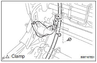
- Disengage the clamp.
- Remove the 2 screws and the reclining adjuster inside cover RH (lower).
24. REMOVE RECLINING ADJUSTER INSIDE COVER LH
- Remove the screw and the reclining adjuster inside cover LH (upper).
25. REMOVE RECLINING ADJUSTER INSIDE COVER RH
HINT: Use the same procedures for the RH side and LH side.
26. REMOVE FRONT SEAT CUSHION SHIELD LOWER LH
- Remove the screw and the front seat cushion shield lower LH.
27. REMOVE FRONT SEAT CUSHION SHIELD LOWER RH
HINT: Use the same procedures for the RH side and LH side.
28. REMOVE LUMBAR SUPPORT ADJUSTER ASSEMBLY LH (for Driver Seat)
- Disconnect the connector.
- Remove the 2 screws and the lumbar support adjuster assembly LH.
29. REMOVE SEAT POSITION AIRBAG SENSOR (for Driver Seat)
 Removal
NOTICE:
Always wear safety gloves because the edges of the
seatback frame and seat adjuster are sharp and may
cause injury.
Work must be started more than 90 seconds after the
...
 Reassembly
1. INSTALL SEAT POSITION AIRBAG SENSOR (for Driver Seat)
2. INSTALL LUMBAR SUPPORT ADJUSTER
ASSEMBLY LH
Install the seat side table leg cover.
3. INSTALL FRONT SEAT CUSHION SHIELD LOWER LH
...
Other materials:
DVD Player Mechanical Error/ DVD Insertion and Ejection Error/ DVD Reading
Abnormal
DTC 44-10 DVD Player Mechanical Error
DTC 44-11 DVD Insertion and Ejection Error
DTC 44-12 DVD Reading Abnormal
DESCRIPTION
TC No.
DTC Detection Condition
Trouble Area
44-10
A mechanical error in the DVD player is detected while
the DVD is not being insert ...
Problem symptoms table
HINT:
Proceed to the troubleshooting for each circuit in the table
below.
AIRBAG SYSTEM
Symptom
Suspected Area
The SRS warning light goes off after the primary
check, but then comes on.
SRS Warning Light Remains ON
When the ignition switch is turned to t ...
Diagnosis system
1. CHECK DLC3
The vehicle's ECU uses ISO 15765-4 for
communication protocol. The terminal arrangement
of the DLC3 complies with SAE J1962 and matches
the ISO 15765-4 format.
NOTICE:
*: Before measuring the resistance, leave the
vehicle as is for at least 1 minute and do not
...
