Toyota Sienna Service Manual: Disassembly
1. REMOVE REAR DOOR WINDOW FRAME MOULDING REAR LH (See page ET-31)
2. REMOVE REAR DOOR WINDOW FRAME MOULDING SUB-ASSEMBLY LH (See page ET-32)
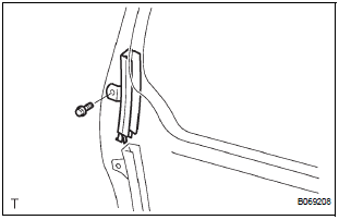
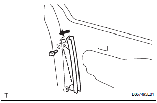
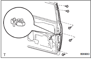
3. REMOVE SLIDE DOOR WINDOW GARNISH LH
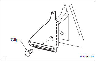
- Fully open the slide door window.
- Remove the glass run.
- Using a screwdriver, disengage the clip and remove
the garnish.
HINT: Tape the screwdriver tip before use.
- Using a screwdriver, disengage the 2 claws and
remove the weatherstrip inner from the garnish.
HINT: Tape the screwdriver tip before use.
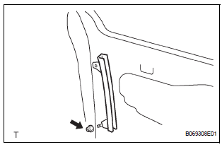
4. REMOVE SIDE TRIM BOARD COVER REAR LH
- Remove the 2 screws.
- Using a screwdriver, disengage the 8 claws and
remove the cover together with the window control
switch.
HINT: Tape the screwdriver tip before use.
- Remove the 2 screws and window control switch.
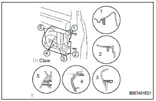
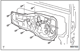
5. REMOVE REAR DOOR TRIM BOARD SUBASSEMBLY LH
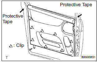
- Remove the screw.
- Using a screwdriver, disengage the 9 clips and remove the trim board.
HINT:
- Tape the screwdriver tip before use.
- In order to prevent the door panel from being damaged, cover the areas with protective tape as indicated by arrow marks in the illustration.
- Using a clip remover, remove the 6 clips and weatherstrip No. 2.
- Using a screwdriver, disengage the 11 claws and remove the weatherstrip inner from trim board.
HINT: Tape the screwdriver tip before use.
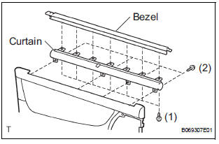
- w/ Sunshade: Remove the sunshade.
- Remove the 7 screws and sunshade bezel.
- Remove the 4 screws and curtain.
6. REMOVE SLIDE DOOR WINDOW ASSEMBLY LH
- w/ Sunshade: Remove the sun shade hook.
- Remove the bolt and window frame.
- Remove the bolt.
- Loosen the nut.
- Push the window frame rear lower in the direction indicated by the arrow mark in the illustration.
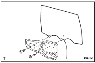
- Remove the 2 hole plugs.
- Move the window until the bolts appear in the service holes.
NOTICE:
- Do not damage the window.
- When the bolts are removed, the window may fall and become deformed.
- Remove the 2 bolts and window.
7. REMOVE REAR DOOR GLASS WEATHERSTRIP ASSEMBLY OUTER LH (See page ET-23)
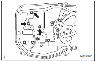
8. REMOVE SLIDE DOOR ATTACHMENT CONTROL LH
- Remove the 2 screws, bolt and inside handle.
- Disconnect the connectors from the lock actuator, the power window regulator motor and lock release motor and power slide door lock.
- Disengage the control wires.
- Remove the 8 bolts and attachment control.
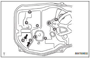
- Remove the nut and window frame rear lower.
NOTICE: When the nut is removed, the window frame may fall and become deformed.
HINT: Remove the window frame rear lower through the service hole.
- Remove the control rod.
- Remove the 3 bolts and lock remote control.
- Remove the 2 screws and lock actuator.
- Remove the 2 screws and lock release motor.
- Remove the 3 screws and power window regulator motor.
- Remove the half stop control lever and door lock control bellcrank.
- Remove the 4 bolts and the window regulator.
9. REMOVE REAR DOOR OUTSIDE HANDLE COVER LH
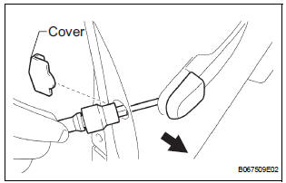
- Remove the outside handle hole cover.
- Using a torx socket wrench (T30), loosen the screw and remove the outside handle cover with the lock key cylinder installed
10. REMOVE REAR DOOR OUTSIDE HANDLE ASSEMBLY LH
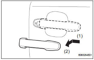
- Pushing and pulling the outside handle in the direction indicated by the arrow mark in the illustration, remove the outside handle.
- Remove the outside handle pads front and rear.
11. REMOVE REAR DOOR OUTSIDE HANDLE FRAME SUB-ASSEMBLY LH
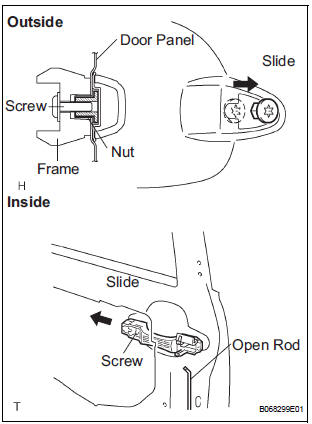
- Remove the open rod to the outside handle frame.
- Using a torx socket wrench (T30), loosen the screw.
- Slide the outside handle frame in the direction indicated by the arrow mark in the illustration and remove it.
HINT: Remove the outside handle frame through the service hole.
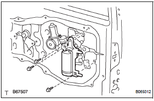
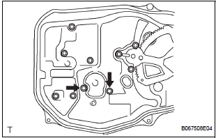
12. REMOVE POWER SLIDE DOOR CONTROL MOTOR AND CLUTCH
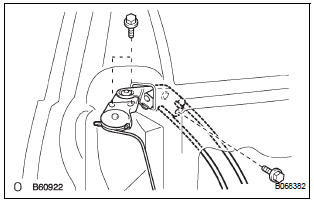
- Remove the 3 bolts from the upper part of the control motor and clutch.
- Remove the 2 clips and 4 bolts from the lower part of the control motor and clutch.
- Remove the control motor and clutch.
HINT: Remove the motor and clutch through the service hole.
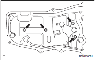
13. REMOVE REAR DOOR STIFFENER CUSHION LH
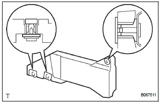
- Remove the 2 screws, clip and stiffener cushion.
HINT: Remove the stiffener cushion through the service hole.
- Remove the 2 grommets and 2 clips.
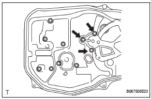
14. REMOVE SLIDE DOOR LOCK ASSEMBLY FRONT LH
- Disconnect the 2 cables.
- Using a torx socket wrench (T30), remove the 3 screws and lock.
HINT: Remove the lock front through the service hole.
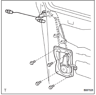
15. REMOVE POWER SLIDE DOOR LOCK ASSEMBLY LH
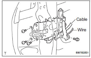
- Disconnect the cable and wire.
- Using a torx socket wrench (T30), remove the 3 screws.
- Remove the bolt and lock.
HINT: Remove the lock through the service hole.
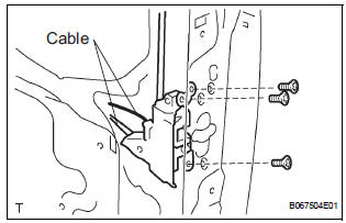
16. REMOVE REAR DOOR WIRE SUB-ASSEMBLY LH
- Remove the 2 screws.
- Using a screwdriver, remove the 2 clips and wire.
HINT: Tape the screwdriver tip before use.
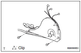
17. REMOVE POWER SLIDE DOOR ECU LH
- Remove the 2 screws and power slide door ECU with the warning buzzer.
- Disengage the claw and remove the warning buzzer.
18. REMOVE POWER SLIDE DOOR TOUCH SENSOR LH
- Disconnect the connector.
- Remove the 5 screws and touch sensor.
 Removal
HINT:
On the RH side, use the same procedures as on the LH side.
1. REMOVE SLIDE DOOR
Remove the rear door scuff plate (See page IR-7).
Remove the back door scuff plate (See page ED-
214 ...
 Adjustment
HINT:
On the RH side, use the same procedures as on the LH side.
1. INSPECT SLIDE DOOR PANEL SUB-ASSEMBLY LH
Check that the clearance is within the standard
range.
Standard
2. ADJUST ...
Other materials:
How to proceed with
troubleshooting
HINT:
Use these procedures to troubleshoot the power door lock
control system.
The intelligent tester should be used in steps 4 and 5.
1 VEHICLE BROUGHT TO WORKSHOP
2 CUSTOMER PROBLEM ANALYSIS CHECK
HINT:
In troubleshooting, confirm that the problem symptoms
have ...
Removal
1. DRAIN POWER STEERING FLUID
2. REMOVE FRONT WHEEL RH
3. REMOVE FRONT FENDER APRON SEAL RH (See
page EM-26)
4. REMOVE FAN AND GENERATOR V BELT (See page
EM-6)
5. DISCONNECT NO. 1 FLUID RESERVOIR TO PUMP HOSE
(a) Slide the clip and disconnect the No. 1 fluid
reservoir to pump hose from t ...
Installation
1. INSTALL FRONT SUSPENSION ARM SUBASSEMBLY LOWER NO.1 LH
(a) Install the front lower arm bush stopper to the front
suspension arm sub-assembly lower No.1 LH.
(b) Install the bolt and nut to the rear side of the front
suspension arm sub-assembly lower No.1 LH.
Torque: 206 N*m (2,100 kgf ...
