Toyota Sienna Service Manual: Disassembly
1. Remove repair service starter kit
(a) Remove the nut and disconnect the lead wire from the repair service starter kit.
(b) Remove the 2 screws which are used to secure the repair service starter kit to the repair service starter kit.
(c) Remove the repair service starter kit.
(d) Remove the return spring and the plunger from the repair service starter kit.
2. REMOVE STARTER YOKE ASSEMBLY
(a) Remove the 2 through bolts and pull out the starter yoke together with the starter commutator end frame.
(b) Remove the starter yoke from the starter commutator end frame.
3. REMOVE STARTER ARMATURE PLATE
(a) Remove the starter armature plate from the starter yoke.
4. REMOVE DRIVE HOUSING STARTER BEARING COVER
(a) Using a screwdriver, remove the drive housing starter bearing cover.
5. REMOVE STARTER ARMATURE ASSEMBLY
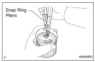
(a) Using snap ring pliers, remove the snap ring and plate washer.
(b) Remove the starter armature from the commutator end frame.
6. REMOVE PLANETARY GEAR
(a) Remove the 3 planetary gears from the repair service starter kit.
 Removal
1. REMOVE BATTERY (See page EM-26)
2. REMOVE NO. 2 AIR CLEANER INLET (See page EM-
28)
3. REMOVE AIR CLEANER CAP SUB-ASSEMBLY (See
page FU-13)
4. REMOVE AIR CLEANER FILTER ELEMENT (See page
EM-2 ...
 Inspection
1. Inspect starter assembly
NOTICE:
These tests must be performed within 3 to 5 seconds
to avoid burning out the coil.
(a) Perform the pull-in test.
(1) Disconnect the lead ...
Other materials:
Inspection
1. INSPECT VENTILATION VALVE
(a) Install a clean hose to the ventilation valve.
(b) Check the ventilation valve operation.
(1) Blow air into the cylinder head side, and check
that air passes through easily.
NOTICE:
Do not suck air through the valve.
Petroleum substances i ...
Short in Side Squib LH Circuit
DTC B0115/47 Short in Side Squib LH Circuit
DESCRIPTION
The side squib LH circuit consists of the center airbag sensor assembly and
the front seat side airbag
assembly LH.
This circuit instructs the SRS to deploy when deployment conditions are met.
DTC B0115/47 is recorded when a short ci ...
Problem symptoms table
HINT:
Use the table below to help determine the cause of the
problem symptom. The likely causes of the problem are
indicated in descending order. Check each suspected area
in order. Repair or replace faulty parts or perform
adjustments as necessary.
Inspect the fuse and rel ...
