Toyota Sienna Service Manual: Disassembly
1. REMOVE PROPELLER SHAFT ASSEMBLY
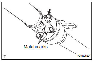
(a) Put matchmarks on both the flanges.
(b) Remove the 4 nuts, bolts and washers.
2. REMOVE INTERMEDIATE SHAFT
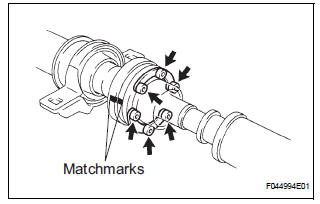
(a) Put matchmarks on the propeller shaft subassembly and universal joint flange.
NOTICE: Do not use a punch for the marks.
(b) Using a hexagon wrench (6 mm), remove the 6 bolts and 2 washers and separate the intermediate shaft from the propeller shaft assembly rear.
3. REMOVE CENTER SUPPORT BEARING ASSEMBLY NO.1
(a) Using a chisel and a hammer, loosen the staked part of the nut.
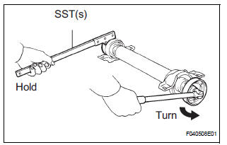
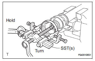
(b) Using SST(s) to hold the front flange, remove the nut and plate washer.
SST 09330-00021
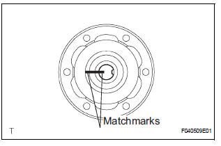
(c) Put matchmarks on the rear flange and shaft.
(d) Hold the intermediate shaft in a vise between aluminium plates.
NOTICE: Do not overtighten the vise
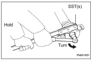
(e) Using SST(s), remove the rear flange.
SST 09950-40011 (09951-04020, 09952-04010, 09953-04030, 09954-04010, 09955-04061, 09957-04010, 09958-04011)
NOTICE: Be careful not to damage the universal joint flange.
(f) Remove the center support bearing assembly No. 1 (rear) and washer.
4. REMOVE CENTER SUPPORT BEARING ASSEMBLY NO.1
(a) Using a chisel and a hammer, loosen the staked part of the nut.
(b) Using SST(s) to hold the front flange, remove the nut and plate washer.
SST 09330-00021
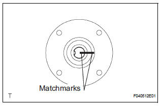
(c) Put matchmarks on the front flange and shaft.
(d) Hold the intermediate shaft in a vise between aluminium plates.
NOTICE: Do not overtighten the vise.
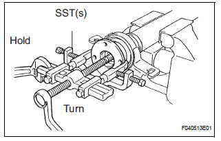
(e) Using SST(s), remove the front flange.
SST 09950-40011 (09951-04020, 09952-04010, 09953-04030, 09954-04010, 09955-04061, 09957-04010, 09958-04011)
NOTICE: Be careful not to damage the universal joint flange.
(f) Remove the center support bearing assembly No. 1 (front) and washer.
 Removal
1. REMOVE EXHAUST PIPE ASSEMBLY
(a) Remove exhaust pipe assembly (See page EX-8).
2. REMOVE PROPELLER W/CENTER BEARING SHAFT ASSEMBLY
(a) Depress the brake pedal and hold it down.
(b) Using ...
 Inspection
1. INSPECT SPIDER BEARING
(a) Check that the spider bearing moves smoothly by
turning the flange.
(b) Check for the looseness around the joint by strongly
moving the flange in the axial and ...
Other materials:
Reassembly
1. INSTALL COOLER DRYER
(a) Using needle nose pliers, install the cooler dryer.
(b) Install a new O-ring on the cap.
(c) Sufficiently apply compressor oil to the fitting
surfaces of the O-ring and the cap.
Compressor oil:
ND-OIL 8 or equivalent
(d) Using a hexagon wrench 14 mm ( ...
Headlight leveling switch
ON-VEHICLE INSPECTION
1. HEADLIGHT LEVELING SWITCH
Connect the battery positive (+) lead to the terminal
1 and the battery negative (-) lead to the terminal 5.
Measure the resistance between the terminal 4 and
the battery negative (-) lead when headlight leveling
switch ...
ACC Power Source Circuit
DESCRIPTION
This circuit supplies power to the A/C amplifier and the illumination for the
clock.
WIRING DIAGRAM
INSPECTION PROCEDURE
1 INSPECT FUSE (ECU ACC)
(a) Remove the ECU ACC fuse from the engine room relay
block.
(b) Measure the resistance according to the value(s) in the
tab ...
