Toyota Sienna Service Manual: Display Signal Circuit between Video Terminal and Television Display
DESCRIPTION
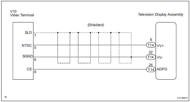
This is the display signal circuit from the video terminal to the television display assembly.
WIRING DIAGRAM
INSPECTION PROCEDURE
1 CHECK HARNESS AND CONNECTOR (TELEVISION DISPLAY ASSEMBLY - VIDEO TERMINAL)
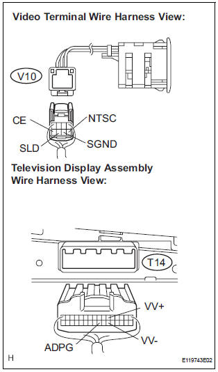
- Disconnect the connectors from the video terminal and television display assembly.
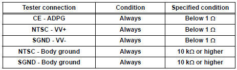
- Measure the resistance according to the value(s) in the table below.
Standard resistance
2 INSPECT VIDEO TERMINAL
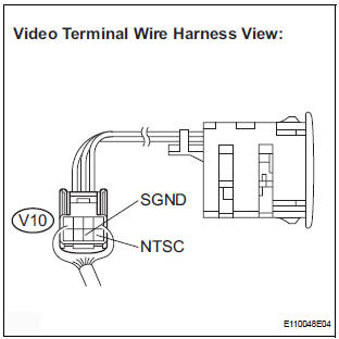
- Reconnect the video (video adapter) terminal connector.
- Measure the waveform according to the table below.
OK
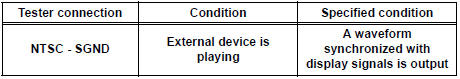
HINT: The waveform pattern may differ from that shown in the illustration below due to differences in oscilloscope setting. A normal video terminal operating condition can be determined if any waveform is output.
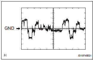
- Oscilloscope waveform
- Terminal: NTSC - Body ground
Setting: 200mV/DIV, 10 μs/DIV
Condition: DVD display is ON.
PROCEED TO NEXT CIRCUIT INSPECTION SHOWN IN PROBLEM SYMPTOMS TABLE
 Sound Signal Circuit between Video Terminal and Television Display
DESCRIPTION
This is the sound signal circuit from the video (video adapter) terminal to
the television display assembly.
WIRING DIAGRAM
INSPECTION PROCEDURE
1 CHECK HARNESS AND CONNECTOR (TE ...
 Television Display Power Source Circuit
DESCRIPTION
This is the power source circuit to operate the television display assembly.
WIRING DIAGRAM
INSPECTION PROCEDURE
1 INSPECT TELEVISION DISPLAY ASSEMBLY
Disconnect the connec ...
Other materials:
Oxygen Sensor Circuit
HINT:
Sensor 2 refers to the sensor mounted behind the Three-Way Catalytic
Converter (TWC) and located far
from the engine assembly.
DESCRIPTION
A three-way catalytic converter (TWC) is used in order to convert the carbon
monoxide (CO), hydro
carbon (HC), and nitrogen oxides (HOx) into ...
ACC Power Source Circuit
DESCRIPTION
This circuit supplies power to the A/C amplifier and the illumination for the
clock.
WIRING DIAGRAM
INSPECTION PROCEDURE
1 INSPECT FUSE (ECU ACC)
(a) Remove the ECU ACC fuse from the engine room relay
block.
(b) Measure the resistance according to the value(s) in the
tab ...
Stowing the third seats (power seats)
You can operate the power third seats when the shift lever is in P.
Before stowing or returning third seat, remove any items from the floor
area to prevent interference with moving parts.
Before stowing the third seats
Lower the center head
restraint to the lowest position and stow th ...
