Toyota Sienna Service Manual: Disposal
HINT: When scrapping a vehicle equipped with the SRS or disposing of the steering pad, be sure to deploy the airbag first in accordance with the procedure described below. If any abnormality occurs with airbag deployment, contact the SERVICE DEPT. of TOYOTA MOTOR SALES, U.S.A., INC.
CAUTION:
- Never dispose of a steering pad that has an undeployed airbag.
- The airbag produces an exploding sound when it is deployed, so perform the operation outdoors and where it will not create a nuisance to nearby residents.
- When deploying the airbag, always use the specified SST (SRS Airbag Deployment Tool). Perform the operation in a place away from electrical noise.
- When deploying the airbag, perform the operation at least 10 m (33 ft) away from the steering pad.
- The steering pad becomes extremely hot when the airbag is deployed, so do not touch it for at least 30 minutes after deployment.
- Use gloves and safety glasses when handling a steering pad with a deployed airbag.
- Do not apply water, etc. to a steering pad with a deployed airbag.
- Always wash your hands with water after completing the operation.
1. DISPOSE OF STEERING PAD (WHEN INSTALLED IN VEHICLE)
HINT: Prepare a battery as the power source to deploy the airbag.
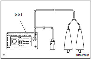
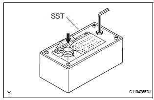
- Check the function of the SST.
SST 09082-00700
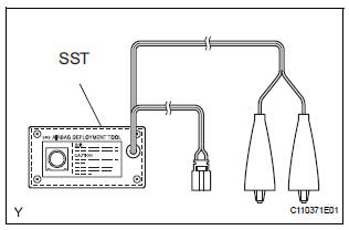
CAUTION: When deploying the airbag, always use the specified SST: SRS Airbag Deployment Tool
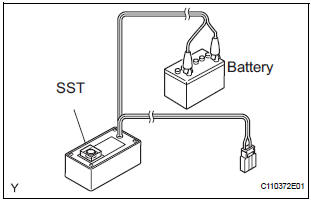
- Connect the SST to the battery.
Connect the red clip of the SST to the battery positive (+) terminal and the black clip of the SST to the negative (-) terminal.
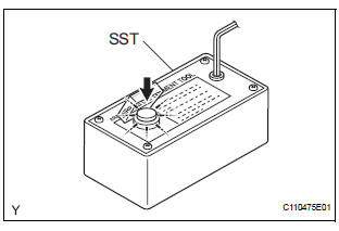
- Check the function of the SST.
Press the SST activation switch, and check that the LED of the SST activation switch comes on.
CAUTION:
- Do not connect the SST connector (yellow colored one) to the airbag.
- If the LED comes on when the activation switch is not being pressed, SST malfunction is possible, so replace the SST with a new one.
- Disconnect the SST from the battery.
- Precaution.
- Disconnect the cable from the negative battery terminal.
CAUTION: Wait for 90 seconds after disconnecting the cable to prevent the airbag working.
- Remove the steering column cover lower.
- While turning the steering wheel assembly to the right and left, remove the 2 screws and steering column cover lower.
- Install the SST.
CAUTION: Check that there is no looseness in the steering wheel assembly and steering pad.
- Disconnect the airbag connector (yellow colored one) from the spiral cable.
NOTICE: When handling the airbag connector, take care not to damage the airbag wire harness.
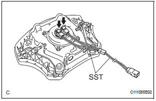
- Connect the SST connector to the airbag
connector of the spiral cable.
SST 09082-00700, 09082-00780
NOTICE: To avoid damaging the SST connector and wire harness, do not lock the secondary lock of the twin lock.
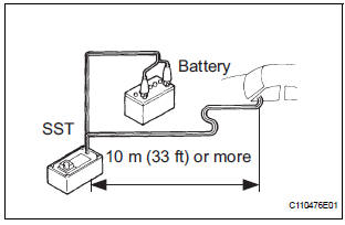
- Move the SST at least 10 m (33 ft) away from the vehicle front side window.
- Maintaining enough clearance for the SST wire harness in the front side window, close all doors and windows of the vehicle.
NOTICE: Take care not to damage the SST wire harness.
- Connect the red clip of the SST to the battery positive (+) terminal and the black clip of the SST to the negative (-) terminal.
- Deploy the airbag.
- Check that no one is inside the vehicle or within a 10 m (33 ft) radius of the vehicle.
- Press the SST activation switch and deploy the airbag.
CAUTION:
- When deploying the airbag, make sure that no one is near the vehicle.
- The steering pad becomes extremely hot when the airbag is deployed, so do not touch it for at least 30 minutes after deployment.
- Use gloves and safety glasses when handling a steering pad with a deployed airbag.
- Do not apply water, etc. to a steering pad with a deployed airbag.
- Always wash your hands with water after completing the operation.
HINT: The airbag is deployed as the LED of the SST activation switch comes on.
2. DISPOSE OF STEERING PAD (WHEN NOT INSTALLED IN VEHICLE)
NOTICE:
- When disposing of the steering pad, never use the customer's vehicle to deploy the airbag.
- Be sure to follow the procedure detailed below when deploying the airbag.
HINT: Prepare a battery as the power source to deploy the airbag.
- Check the function of the SST.
SST 09082-00700
CAUTION: When deploying the airbag, always use the specified SST: SRS Airbag Deployment Tool
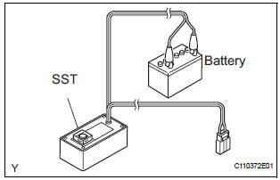
- Connect the SST to the battery.
Connect the red clip of the SST to the battery positive (+) terminal and the black clip of the SST to the negative (-) terminal.
- Check the function of the SST.
Press the SST activation switch, and check that the LED of the SST activation switch comes on.
CAUTION:
- Do not connect the SST connector (yellow colored one) to the airbag.
- If the LED comes on when the activation switch is not being pressed, SST malfunction is possible, so replace the SST with a new one.
- Disconnect the SST from the battery.
- Remove the steering pad.
CAUTION:
- When removing the steering pad, work must be started 90 seconds after the ignition switch is turned to the "LOCK" position and the negative (-) terminal cable is disconnected from the battery.
- When storing the steering pad, keep the airbag deployment side facing upward.
- Using a service-purpose wire harness for the vehicle, tie down the steering pad to the disc wheel.
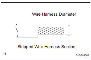
Wire harness: Stripped wire harness section: 1.25 mm2 or more (0.0019 in.2 or more) CAUTION: If the wire harness is too thin or an alternative object is used to tie down the steering pad, it may be snapped by the shock when the airbag is deployed. Always use a wire harness for vehicle use with an area of at least 1.25 mm2 (0.0019 in.2).
HINT: To calculate the area of the stripped wire harness section: Area = 3.14 x (Diameter)2 divided by 4
- Install the 2 bolts with washers into the 2 bolt holes on the steering pad.
Bolt:
L:
35.0 mm (1.378 in.)
M:
6.0 mm (0.236 in.)
Pitch:
1.0 mm (0.039 in.)
NOTICE:
- Tighten the bolts by hand until they become difficult to turn.
- Do not tighten the bolts excessively.
- After connecting the SST below to each other,
connect them to the steering pad.
SST 09082-00802 (09082-10801, 09082- 30801)
- Using 3 wire harnesses, wind wire harness at least 2 times each around each of the bolts installed on the left and right sides of the steering pad.
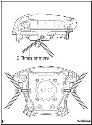
CAUTION:
- Tightly wind the wire harness around the bolts so that there is no slack.
- Make sure that the wire harness is tight.
If there is slack in the wire harness, the steering pad may become loose due to the shock when the airbag is deployed.
- Face the airbag deployment side of the steering pad upward on top of a tire and wheel set. Separately tie the left and right sides of the steering pad to the disc wheel through the hub nut holes. Position the SST connector so that it hangs downward through the hub hole of the disc wheel.
CAUTION:
- Make sure that the wire harness is tight.
If there is slack in the wire harness, the steering pad may become loose due to the shock when the airbag is deployed.
- Always tie down the steering pad with the airbag deployment side facing upward.
NOTICE: The disc wheel will be damaged by airbag deployment, so use an extra disc wheel.
- Install the SST.
CAUTION: Place the disc wheel on level ground.
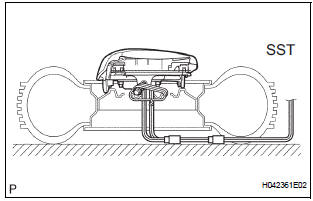
- Connect the SST connector.
SST 09082-00700 NOTICE: To avoid damaging the SST connector and wire harness, do not lock the secondary lock of the twin lock. Also, secure some slack for the SST wire harness inside the disc wheel.
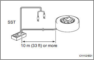
- Move the SST at least 10 m (33 ft) away from the airbag tied down to the tire
- Cover the steering pad (Using a cardboard box).
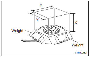
- Cover the steering pad with the cardboard box.
- Place weights on the cardboard box in 4 places
totalling at least 190 N (19 kg, 43 lb).
Cardboard box size:
Must exceed the following dimensions
X: 460 mm (18.11 in.)
Y: 650 mm (25.59 in.)
NOTICE:
- When the dimension Y of the cardboard
box exceeds the diameter of the disc
wheel with tire which the steering pad is
tied to, X should be the following size.
X = 460 mm (18.11 in.) + width of tire
- If a cardboard box which is smaller than the specified size is used, the cardboard box will be broken by the shock from airbag deployment.
- Cover the steering pad (Using tires).
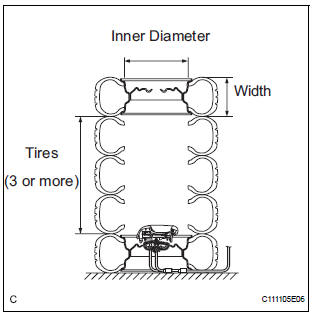
- Place at least 3 tires without disc wheels on the tire with disc wheel which the steering pad is tied to.
- Place the tire with a disc wheel on top of them.
Tire size:
Must exceed the following dimensions
Width: 185 mm (7.28 in.)
Inner diameter: 360 mm (14.17 in.)
CAUTION: Do not use tires with disc wheels except for on the top and bottom.
NOTICE:
- The tires may be damaged by airbag deployment, so use an extra tire.
- Do not place the SST connector under the tire because it could be damaged.
- Tie the tires together with 2 wire harnesses.
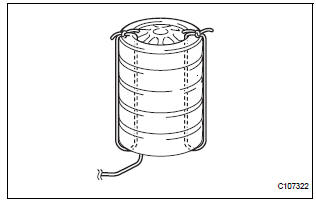
CAUTION: Make sure that the wire harness is tight.
Looseness in the wire harness results in the tires coming free due to the shock when the airbag is deployed.
- Deploy the airbag.
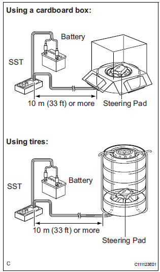
- Connect the red clip of the SST to the battery positive (+) terminal and the black clip of the SST to the negative (-) terminal.
- Check that no one is within a 10 m (33 ft) radius of the disc wheel which the steering pad is tied to.
- Press the SST activation switch and deploy the airbag.
CAUTION: When deploying the airbag, make sure that no one is near the tire.
HINT: The airbag is deployed as the LED of the SST activation switch comes on.
- Dispose of the steering pad.
CAUTION:
- The steering pad becomes extremely hot when the airbag is deployed, so do not touch it for at least 30 minutes after deployment.
- Use gloves and safety glasses when handling a steering pad with a deployed airbag.
- Do not apply water, etc. to a steering pad with a deployed airbag.
- Always wash your hands with water after completing the operation.
- Remove the steering pad from the disc wheel.
- Place the steering pad in a plastic bag, tie it tightly and dispose of it as other general part disposal.
 Installation
1. INSTALL STEERING PAD
Support the steering pad with one hand as shown in
the illustration.
Connect the 2 connectors to the steering pad.
NOTICE:
When handling the airba ...
 Spiral cable
COMPONENTS
...
Other materials:
Adjustment
HINT:
On the RH side, use the same procedures as on the LH side.
1. INSPECT SLIDE DOOR PANEL SUB-ASSEMBLY LH
Check that the clearance is within the standard
range.
Standard
2. ADJUST SLIDE DOOR PANEL SUB-ASSEMBLY LH
Using the SST, horizontally and vertically adjust the
...
Crankshaft Position - Camshaft Position Correlation
DTC P0016 Crankshaft Position - Camshaft Position Correlation
(Bank 1 Sensor A)
DTC P0017 Crankshaft Position - Camshaft Position Correlation
(Bank 1 Sensor B)
DTC P0018 Crankshaft Position - Camshaft Position Correlation
(Bank 2 Sensor A)
DTC P0019 Crankshaft Position - Camshaft Position Corr ...
Power Slide Door does not Fully Open
DESCRIPTION
When the LH / RH rear window is open 105 mm (5.91 in.) or more,
the slide door half-open stopper is
activated to force the slide door to stop at approximately 105 mm (5.91 in.)
from the fully open position.
This is caused by the jam protection function between the sli ...
