Toyota Sienna Service Manual: Driver Side Outer Mirror
DTC B1209 Driver Side Outer Mirror
DESCRIPTION
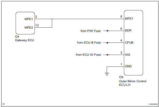
This DTC is detected when communication between the outer mirror control ECU LH and multiplex network gateway ECU stops for more than 10 seconds
|
DTC No. |
DTC Detection Condition |
Trouble Area |
|
B1209 |
Driver side outer mirror ECU communication stops |
|
WIRING DIAGRAM
INSPECTION PROCEDURE
1 CHECK HARNESS AND CONNECTOR (OUTER MIRROR CONTROL ECU LH - BATTERY)
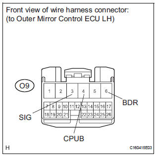
- Disconnect the O9 ECU connector.
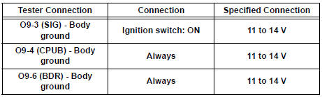
- Measure the voltage according to the value(s) in the table below.
Standard voltage
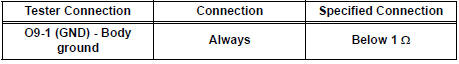
2 CHECK HARNESS AND CONNECTOR (OUTER MIRROR CONTROL ECU LH - GROUND)
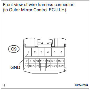
- Measure the resistance according to the value(s) in the table below.
Standard resistance
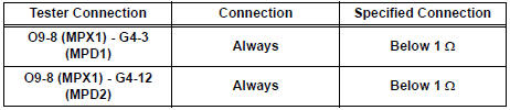
3 CHECK COMMUNICATION LINE
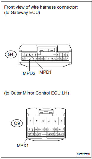
- Disconnect the G4 ECU connector.
- Measure the resistance according to the value(s) in the table below.
Standard resistance
Result
REPLACE OUTER MIRROR CONTROL ECU LH
 Passenger Side Outer Mirror ECU
DTC B1208 Passenger Side Outer Mirror ECU
DESCRIPTION
This DTC is detected when communication between the outer mirror control ECU
RH and multiplex
network gateway ECU stops for more than 10 seco ...
 Short to B+ in Door System Communication
Bus Malfunction/ Short to GND in Door System Communication
Bus Malfunction
Short to B+ in Door System Communication
Bus Malfunction/ Short to GND in Door System Communication
Bus Malfunction
DTC B1214 Short to B+ in Door System Communication
Bus Malfunction
DTC B1215 Short to GND in Door System Communication
Bus Malfunction
DESCRIPTION
DTCs B1214 and B1215 are output when a short to ...
Other materials:
Reassembly
1. INSTALL NO. 2 SEAT LEG SUB-ASSEMBLY
Install the No. 2 seat leg sub-assembly with the 3
bolts and nut.
Torque: 19 N*m (194 kgf*cm, 14 ft.*lbf)
NOTICE:
Tighten the bolts and nuts in the order shown in
the illustration.
Install the 3 clamps.
2. INSTALL NO. 2 SEAT ...
Fuel pump resistor
Components
REMOVAL
1. REMOVE FUEL PUMP RESISTOR
(a) Disconnect the connector.
(b) Remove the nut and fuel pump resistor.
INSPECTION
1. INSPECT FUEL PUMP RESISTOR
(a) Inspect fuel pump resistor.
(1) Using an ohmmeter, measure the resistance
between the terminals.
Standard resi ...
Disassembly
1. REMOVE 2ND BRAKE PISTON RETURN SPRING
SUB-ASSEMBLY
(a) Place SST on the return spring and compress the
return spring with a press.
SST 09387-00060
(b) Using a screwdriver, remove the snap ring.
(c) Remove the 2nd brake piston return spring.
2. REMOVE 2ND BRAKE PISTON
(a) Hold ...
