Toyota Sienna Service Manual: Driving Position Memory Switch Circuit (w/ Memory)
DESCRIPTION
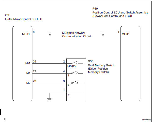
The seat memory switch sends signals to the outer mirror control ECU LH via the multiplex communication system to memorize a given seat position. This memory system does not use a position sensor. The seat position is detected by counting pulses that are output when the motor turns. If there is no pulse output from the motor, the motor will stop operating. The seat memory switch is later used to send signals to the front power seat switch to return the seat to one of the memorized positions.
The power seat memory operation can be performed only when the ignition switch is on and the shift lever is in the P position.
WIRING DIAGRAM
INSPECTION PROCEDURE
1 READ VALUE OF INTELLIGENT TESTER
- Connect the intelligent tester (with CAN VIM) to the DLC3.
- Turn the ignition switch on.
- Read the DATA LIST.
D_SEAT (Position control ECU and switch assembly)
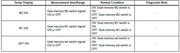
OK: Condition status can be displayed.
PROCEED TO NEXT CIRCUIT INSPECTION SHOWN IN PROBLEM SYMPTOMS TABLE
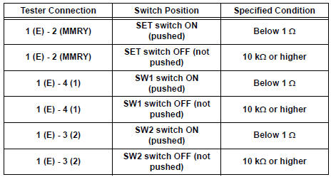
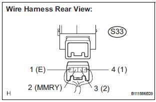
2 INSPECT SEAT MEMORY SWITCH (DRIVING POSITION MEMORY SWITCH)
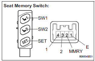
- Remove the seat memory switch.
- Measure the resistance according to the value(s) in the table below.
Standard resistance
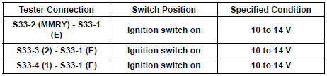
3 CHECK HARNESS AND CONNECTOR (SEAT MEMORY SWITCH CIRCUIT)
- Measure the voltage according to the value(s) in the table below.
Standard voltage
PROCEED TO NEXT CIRCUIT INSPECTION SHOWN IN PROBLEM SYMPTOMS TABLE
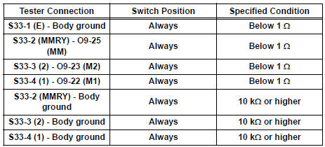
4 CHECK HARNESS AND CONNECTOR (OUTER MIRROR CONTROL ECU LH - SEAT MEMORY SWITCH)
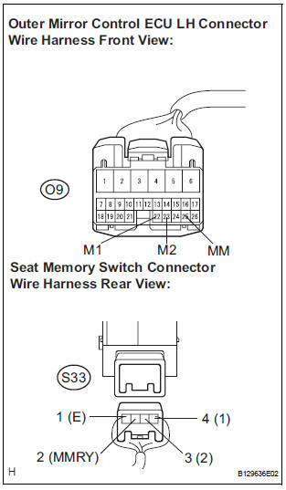
- Disconnect outer mirror control ECU LH connector.
- Measure the resistance according to the value(s) in the table below.
Standard resistance
REPLACE OUTER MIRROR CONTROL ECU LH
 Power Seat Motor Circuit
DESCRIPTION
When the power seat control switch is operated, a command signal is sent to
the position control ECU
and switch assembly (power seat control switch and ECU). The front power seat
swi ...
 ECU Power Source Circuit
DESCRIPTION
The position control ECU and switch assembly (power seat control switch and
ECU) is contained in the
switch assembly.
During manual operation, only one switch signal is accepted. If ...
Other materials:
Occupant Classification System Malfunction
DTC B1150/23 Occupant Classification System Malfunction
DESCRIPTION
The occupant classification system circuit consists of the center airbag
sensor assembly and the occupant
classification ECU.
If the center airbag sensor assembly receives signals from the occupant
classification ECU, it d ...
Removal
HINT:
Replace the RH side using the same procedures as for the
LH side.
1. REMOVE FRONT WHEEL
2. REMOVE FRONT AXLE HUB LH NUT (See page DS-
5)
3. SEPARATE SPEED SENSOR FRONT LH (See page
DS-5)
4. SEPARATE FRONT DISC BRAKE CALIPER ASSEMBLY LH
(a) Remove the 2 bolts and separate the front ...
Folding and extending the mirrors
Manual type
Push the mirror back in the direction
of the vehicle’s rear.
Power type
Press the switch.
Folding
Extending
...
