Toyota Sienna Service Manual: DRL Relay Circuit
DESCRIPTION
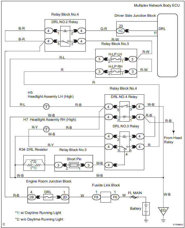
The Multiplex network body ECU controls the DRL No.2 relay
WIRING DIAGRAM
INSPECTION PROCEDURE
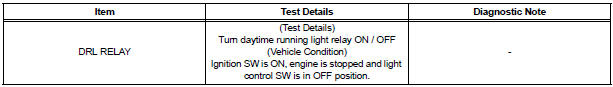
1 PERFORM ACTIVE TEST BY INTELLIGENT TESTER
- Connect the intelligent tester to DLC3.
- Turn the ignition switch ON and push the intelligent tester main switch ON.
- Select the item below in the ACTIVE TEST and then check that the relay operates.
BODY NO.1:
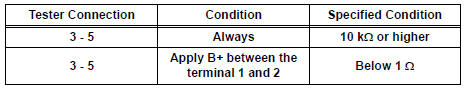
2 INSPECT DRL NO.2 RELAY
- Inspect DRL No.2 Relay continuity.
Resistance
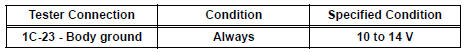
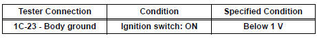
3 CHECK HARNESS AND CONNECTOR (POWER SOURCE)
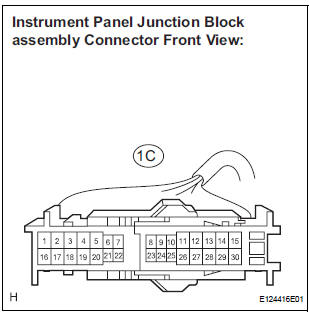
- Disconnect the connector from the instrument panel junction block assembly.
- Measure the voltage according to the value(s) in the table below.
Voltage
4 INSPECT INSTRUMENT PANEL JUNCTION BLOCK ASSEMBLY
- Reconnect the connector to the instrument panel junction block assembly.
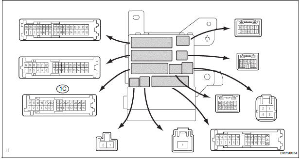
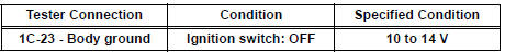
- Measure the voltage according to the value(s) in the table below.
Voltage
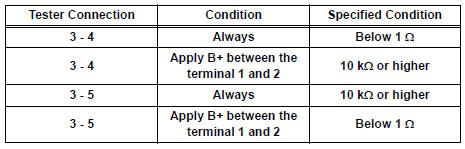
5 INSPECT RELAY (DRL NO.3, DRL NO.4)
- Inspect DRL NO.4 Relay continuity.
Resistance
- Inspect DRL NO.3 Relay continuity.
Resistance
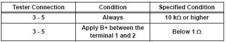
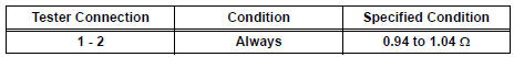
6 INSPECT DAYTIME RUNNING LIGHT RESISTER
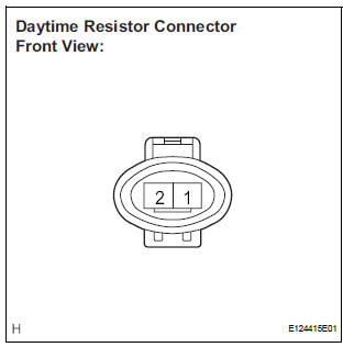
- Measure the resistance according to the value(s) in the table below.
Resistance
REPAIR OR REPLACE HARNESS OR CONNECTOR
 Headlight Relay Circuit
DESCRIPTION
The Multiplex network body ECU controls HEAD relay when signal is received
from headlight dimmer
switch assembly.
WIRING DIAGRAM
INSPECTION PROCEDURE
1 PERFORM ACTIVE TEST BY IN ...
 Front Fog Light Circuit
DESCRIPTION
The Multiplex network body ECU controls FOG relay when signal is received
from headlight dimmer
switch assembly.
WIRING DIAGRAM
INSPECTION PROCEDURE
1 PERFORM ACTIVE TEST BY INT ...
Other materials:
Precaution
1. GENERAL PRECAUTION
When using the battery during inspection, do not
bring the positive and negative tester probes too
close to each other as a short circuit may occur.
PARTS LOCATION
SYSTEM DIAGRAM
1. SIGNAL COMMUNICATION TABLE
Driver Side Power Seat (w ...
DVD-ROM Abnormal
DVD-ROM Abnormal
DESCRIPTION
DTC No.
DTC Detection Condition
Trouble Area
44-43
DVD-ROM operation is abnormal.
DVD
Television display assembly
INSPECTION PROCEDURE
HINT:
After the inspection is completed, clear the DTCs ...
Update contacts from phone
Operation methods differ between PBAP compatible and PBAP
incompatible but OPP compatible Bluetooth® phones.
If your cellular phone is neither PBAP nor OPP compatible, the contacts
cannot be transferred.
For PBAP Compatible Bluetooth® Phones
Select “Update Contacts from Phone”.
Che ...
