Toyota Sienna Service Manual: ECM Communication Stop Mode
DESCRIPTION
|
Detection Item |
Symptom |
Trouble Area |
| ECM Communication Stop Mode |
|
|
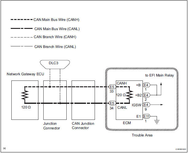
WIRING DIAGRAM
INSPECTION PROCEDURE
NOTICE:
- Turn the ignition switch off before measuring the resistances of CAN bus main wires and CAN bus branch wires.
- After the ignition switch is turned off, check that the key reminder warning system and light reminder warning system are not in operation.
- Before measuring the resistance, leave the vehicle as is for at least 1 minute and do not operate the ignition switch, any other switches, or the doors. If any doors need to be opened in order to check connectors, open the doors and leave them open.
HINT: Operating the ignition switch, any switches, or any doors triggers related ECU and sensor communication with the CAN. This communication will cause the resistance value to change.
1 CHECK OPEN IN CAN BUS WIRE (ECU MAIN BUS WIRE)
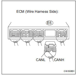
- Disconnect ECM connector (E5).
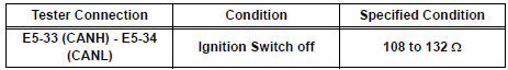
- Measure the resistance according to the value(s) in the table below.
Standard resistance
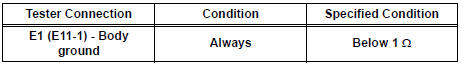
2 CHECK WIRE HARNESS (E1, BATT, +BM, IGSW)
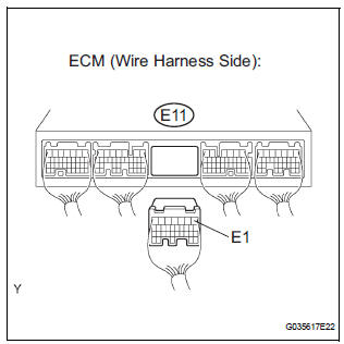
- Disconnect the ECM connector (E11).
- Measure the resistance according to the value(s) in the table below.
Standard resistance
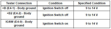
- Disconnect the ECM connector (E4).
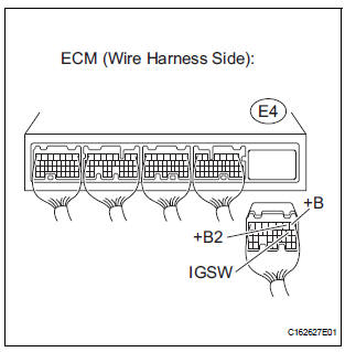
- Measure the voltage according to the value(s) in the table below.
Standard voltage
REPLACE ECM
 Yaw Rate Sensor Communication Stop Mode
DESCRIPTION
Detection Item
Symptom
Trouble Area
Yaw Rate Sensor
Communication Stop
Mode
"Yaw rate/ Deceleration sensor" is not displayed ...
 CAN Bus Line
DESCRIPTION
When any DTC for the CAN communication system is output, first measure the
resistance between the
terminals of the DLC3 to specify the trouble area, and check that there is no
short ...
Other materials:
Safety Connect LED light Indicators
When the engine switch is turned to the “ON” position (vehicles without
a smart key system) or IGNITION ON mode (vehicles with a smart
key system), the red indicator light comes on for 2 seconds then turns
off. Afterward, the green indicator light comes on, indicating that the
service is act ...
Body
GENERAL MAINTENANCE
1. TIGHTEN BOLTS AND NUTS ON CHASSIS AND
BODY
(a) Tighten all the parts of the chassis when necessary.
Steering system
Drive train
Suspension
Brake system
Engine mounting, etc.
(b) Tighten all the parts of the body when necessary.
Seat belts
Seats
Doors ...
Trouble in Passenger Airbag ON / OFF Indicator
DESCRIPTION
The occupant classification system detects the front passenger seat
condition. It then informs a
passenger of the front passenger airbag, the front seat side airbag RH and front
seat belt pretensioner
RH condition (activated/not activated) by the passenger airbag ON/OFF indicator. ...
