Toyota Sienna Service Manual: Electronic control
(a) REMOVAL AND INSTALLATION OF BATTERY TERMINAL
 REMOVAL AND INSTALLATION OF BATTERY TERMINAL
(1) Before performing electronic work, disconnect the cable from the negative (-) battery terminal to prevent component and wire damage caused by accidental short circuits.
(2) When disconnecting the cable, turn the ignition switch and headlight dimmer switch off and loosen the cable nut completely. Perform these operations without twisting or prying the cable.
Then disconnect the cable.
(3) Clock settings, radio settings, audio system memory, DTCs and other data are erased when the cable is disconnected from the negative (-) battery terminal. Write down any necessary data before disconnecting the cable.
(b) HANDLING OF ELECTRONIC PARTS
 HANDLING OF ELECTRONIC PARTS
(1) Do not open the cover or case of the ECU unless absolutely necessary. If the IC terminals are touched, the IC may be rendered inoperative by static electricity.
(2) Do not pull the wires when disconnecting electronic connectors. Pull the connector itself.
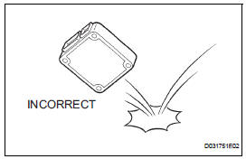
(3) Do not drop electronic components, such as sensors or relays. If they are dropped on a hard surface, they should be replaced.
(4) When cleaning the engine with steam, protect the electronic components, air filter and emission-related components from water.
(5) Never use an impact wrench to remove or install temperature switches or temperature sensors.
(6) When measuring the resistance between terminals of a wire connector, insert the tester probe carefully to prevent terminals from bending.
 For vehicles equipped with srs airbag and seat belt pretensioner
The SIENNA is equipped with a Supplemental Restraint System (SRS).
CAUTION: Failure to carry out the service operations in the correct sequence could cause the SRS to unexpectedly deploy during se ...
 Removal and installation of fuel control parts
(a) PLACE FOR REMOVING AND INSTALLING FUEL
SYSTEM PARTS
(1) Work in a location with good air ventilation that
does not have welders, grinders, drills, electric
motors, stoves, or any other ignitio ...
Other materials:
Removal
1. DISCONNECT BATTERY NEGATIVE TERMINAL
2. REMOVE FRONT DOOR SCUFF PLATE LH
3. REMOVE COWL SIDE TRIM BOARD LH
4. REMOVE INSTRUMENT PANEL FINISH PANEL SUBASSEMBLY
LOWER LH (See page IP-6)
5. REMOVE REAR DOOR SCUFF PLATE RH
6. REMOVE REAR DOOR SCUFF PLATE LH
7. REMOVE FRONT SEAT ASSEMBLY LH
HI ...
Improper Aiming of Radar Sensor Beam Axis
DTC P1572 Improper Aiming of Radar Sensor Beam Axis
DESCRIPTION
This DTC is output when the scanning angle of the laser sensor is incorrect.
This DTC is also output when
the laser sensor beam axis is determined to be in an incorrect position.
DTC No.
DTC Detection Condition
...
Disassembly
1. REMOVE FRONT SEAT SIDE TABLE LEG COVER (w/
Table)
Using a screwdriver, disengage the claws and
remove the seat side table leg cover.
HINT:
Tape the screwdriver tip before use.
2. REMOVE FRONT SEAT SIDE TABLE (w/ Table)
Remove the 4 nuts and seat side table.
Rem ...
