Toyota Sienna Service Manual: Engine Coolant Temperature Receiver Gauge Malfunction
DESCRIPTION
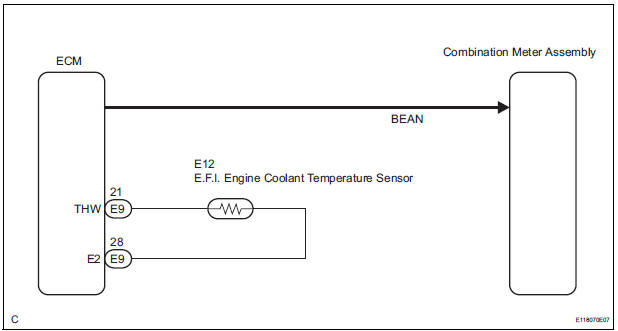
The meter CPU receives engine coolant temperature signals from the ECM via the multiplex communication lines. The meter CPU displays engine coolant temperature that is calculated based on the data received from the ECM.
WIRING DIAGRAM
INSPECTION PROCEDURE
HINT: If there is an open or short in the engine coolant temperature sensor circuit, the ECM will store the DTCs.
Perform troubleshooting of the "SFI System"
1 CHECK MULTIPLEX COMMUNICATION SYSTEM
- Check if the MULTIPLEX communication DTC is output
Result

2 PERFORM ACTIVE TEST BY INTELLIGENT TESTER
- Connect the intelligent tester to the DLC3.
- Turn the ignition switch to the ON position.
- Turn the tester ON.
- Enter the following menus: DIAGNOSIS / OBD/MOBD / METER / ACTIVE TEST.
- Check the operation by referring to the values in the table below.
METER:

OK: Needle indication is normal.
3 READ VALUE OF INTELLIGENT TESTER
- Connect the intelligent tester to the DLC3.
- Turn the ignition switch to the ON position.
- Turn the tester ON.
- Enter the following menus: DIAGNOSIS / ENGINE / DATA LIST.
- Check the values by referring to the values in the table below.
ENGINE:

4 REPLACE COMBINATION METER ASSEMBLY
OK: The operation of the combination meter assembly returns to normal.
END
 Fuel Receiver Gauge Malfunction
DESCRIPTION
The meter CPU uses the fuel sender gauge assembly to determine the level of
the fuel in the fuel tank.
The resistance of the fuel sender gauge will vary between approximately 15 ] ...
 Driver Side Seat Belt Warning Light does not Operate
DESCRIPTION
When turning the ignition switch to the ON position, the combination meter
assembly communicates with
the supplemental restraint system by the multiplex communication system. Unless
...
Other materials:
Diagnostic trouble code chart
HINT:
If a trouble code is displayed during the DTC check,
inspect the circuit listed for that code. For details of the
code, refer to the "See page" in the DTC chart.
Inspect the fuse and relay before investigating the
suspected areas shown in the table below.
W ...
Power window master
switch
Inspection
1. INSPECT POWER WINDOW REGULATOR MASTER SWITCH ASSEMBLY (w/ Jam
Protection Function)
Check the resistance between the terminals of the
switch when the switch is operated.
Standard:
AUTO (driver side) switch
Passenger side switch
Rear LH switch
Rear RH switch
...
No. 1 Ultrasonic sensor
COMPONENTS
REMOVAL
1. REMOVE FRONT FENDER LINER LH
2. REMOVE FRONT FENDER LINER RH
3. REMOVE FRONT BUMPER COVER
4. REMOVE REAR BUMPER COVER (2)
5. REMOVE NO. 1 ULTRASONIC SENSOR RETAINER
Remove the No. 1 ultrasonic sensor retainer as
shown in the illustration
6. REMOVE ...
