Toyota Sienna Service Manual: Entire Combination Meter does not Operate
DESCRIPTION
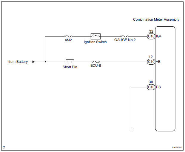
This is the power source circuit to operate the combination meter assembly.
WIRING DIAGRAM
INSPECTION PROCEDURE
1 INSPECT COMBINATION METER ASSEMBLY
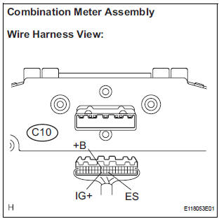
- Disconnect the C10 connector.
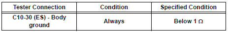
- Measure the resistance according to the value(s) in the table below.
Standard resistance
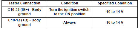
- Measure the voltage according to the value(s) in the table below.
Standard voltage
REPLACE COMBINATION METER ASSEMBLY
 On-vehicle inspection
1. INSPECT SPEEDOMETER
Check the operation.
Using a speedometer tester, check the
speedometer indication according to the table
below.
Reference: mph (U.S.A.)
Referen ...
 Speedometer Malfunction
DESCRIPTION
Factors that affect the indicated vehicle speed include tire size, tire
inflation, and tire wear. The speed indicated on the speedometer has an
allowable margin of error. This can be ...
Other materials:
Disassembly
1. INSPECT PACK CLEARANCE OF FORWARD
CLUTCH
HINT:
(See page AX-242)
2. REMOVE FORWARD MULTIPLE DISC CLUTCH DISC
(a) Using a screwdriver, remove the snap ring.
(b) Remove the flange, 5 discs and 5 plates from the
input shaft assembly.
3. REMOVE FORWARD CLUTCH RETURN SPRING
SUB-ASSEMB ...
Installation
1. INSTALL TRANSFER ASSEMBLY
(a) Apply sealant 1281 to the transaxle assembly and
transfer assembly in continuous beaded from of 1.2
mm diameter as shown in the illustration.
NOTICE:
Wipe any grease off from the attaching
surfaces.
Install it within 10 minutes after applying the
se ...
Reassembly
1. INSTALL 2ND BRAKE PISTON O-RING
(a) Coat 2 new O-rings with ATF, and install them in the
2nd brake piston.
NOTICE:
Make sure that the O-ring is not twisted or
pinched.
2. INSTALL 2ND BRAKE PISTON
(a) Coat the 2nd brake piston with ATF, and install it to
the 2nd brake cylinder.
NO ...
