Toyota Sienna Service Manual: Evaporative Emission Control System Leak Detected
DTC SUMMARY
DESCRIPTION
The circuit description can be found in the EVAP (Evaporative Emission) System (See page ES-409).
INSPECTION PROCEDURE
Refer to the EVAP System (See page ES-412).
MONITOR DESCRIPTION
5 hours*1 after the ignition switch is turned off, the electric vacuum pump creates negative pressure (vacuum) in the EVAP (Evaporative Emission) system. The ECM monitors for leaks and actuator malfunctions based on the EVAP pressure.
HINT:
*1: If the engine coolant temperature is not below 35°C (95°F) 5 hours after the ignition switch is turned off, the monitor check starts 2 hours later. If it is still not below 35°C (95°F) 7 hours after the ignition switch is turned off, the monitor check starts 2.5 hours later.
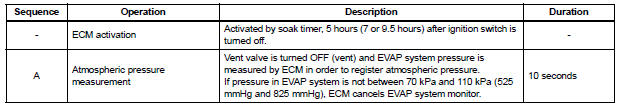
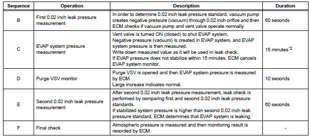
*2: If only a small amount of fuel is in the fuel tank, it takes longer for the EVAP pressure to stabilize.
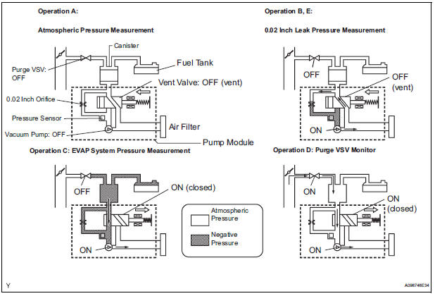
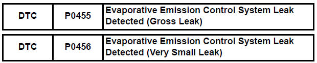
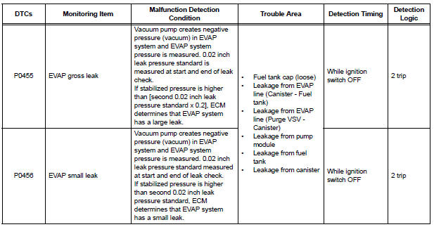
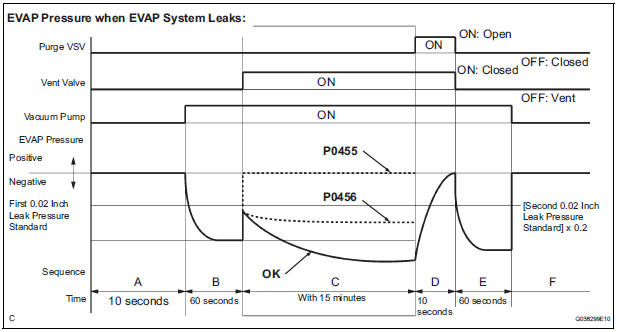
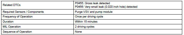
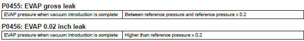
1. P0455: EVAP (Evaporative Emission) gross leak
In operation C, the vacuum pump creates negative pressure (vacuum) in the EVAP system and the EVAP system pressure is measured. If the stabilized system pressure is higher than [second 0.02 inch leak pressure standard x 0.2] (near atmospheric pressure), the ECM determines that the EVAP system has a large leak, illuminates the MIL and sets the DTC (2 trip detection logic).
2. P0456: EVAP very small leak
In operation C, the vacuum pump creates negative pressure (vacuum) in the EVAP system and the EVAP system pressure is measured. If the stabilized system pressure is higher than second 0.02 inch leak pressure standard, the ECM determines that the EVAP system has a small leak, illuminates the MIL and sets the DTC (2 trip detection logic).
MONITOR STRATEGY
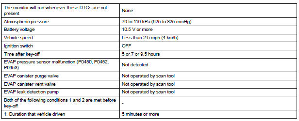
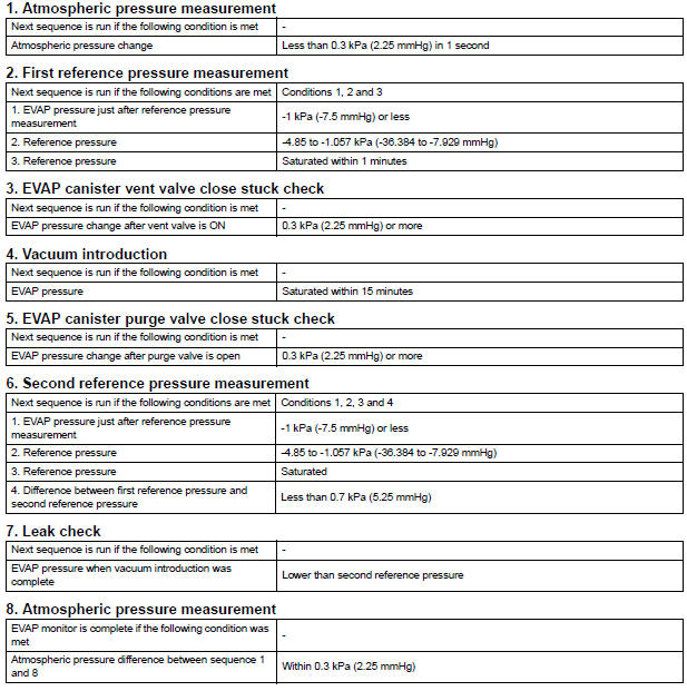
TYPICAL ENABLING CONDITIONS

Key-off monitor sequence 1 to 8
TYPICAL MALFUNCTION THRESHOLDS
MONITOR RESULT
Refer to CHECKING MONITOR STATUS (See page ES-19).
 Evaporative Emission Control System Incorrect Purge Flow
DTC SUMMARY
DESCRIPTION
The circuit description can be found in the EVAP (Evaporative Emission)
System (See page ES-409).
INSPECTION PROCEDURE
Refer to the EVAP System (See page ES-412).
MO ...
 Vehicle Speed Sensor "A"
DESCRIPTION
The speed sensor detects the wheel speed and sends the appropriate signals to
the skid control ECU.
The skid control ECU converts these wheel speed signals into a 4-pulse signal ...
Other materials:
Roof luggage carrier (if equipped)
Roof luggage carrier components
Roof rails
Cross rails
Adjusting the position of cross rails
Turn the knobs counterclockwise
to release the cross
rails.
Slide the cross rails to the
appropriate position for loading
luggage and turn the
knobs clockwise to tigh ...
Short to GND in Front Pretensioner Squib RH
Circuit
DTC B0132/61 Short to GND in Front Pretensioner Squib RH
Circuit
DESCRIPTION
The front pretensioner squib RH circuit consists of the center airbag sensor
assembly and the front seat
outer belt assembly RH.
This circuit instructs the SRS to deploy when deployment conditions are met.
DTC B ...
Display Signal Circuit between Radio and Navigation Assembly and
Television Camera Assembly
DESCRIPTION
This is the display signal circuit of the television camera assembly.
WIRING DIAGRAM
INSPECTION PROCEDURE
1 CHECK HARNESS AND CONNECTOR (RADIO AND NAVIGATION ASSEMBLY - TELEVISION
CAMERA ASSEMBLY)
Disconnect the R10 connector from the radio and
navigation assembly.
&nbs ...
