Toyota Sienna Service Manual: Evaporative Emission System
DTC P043E Evaporative Emission System Reference Orifice Clog Up
DTC P043F Evaporative Emission System Reference Orifice High Flow
DTC P2401 Evaporative Emission System Leak Detection Pump Control Circuit Low
DTC P2402 Evaporative Emission System Leak Detection Pump Control Circuit High
DTC P2419 Evaporative Emission System Switching Valve Control Circuit Low
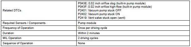
DTC SUMMARY
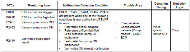
HINT: The 0.02 inch orifice is located inside the pump module.
DESCRIPTION
The circuit description can be found in the EVAP (Evaporative Emission) System.
INSPECTION PROCEDURE
Refer to the EVAP System.
MONITOR DESCRIPTION
5 hours*1 after the ignition switch is turned off, the electric vacuum pump creates negative pressure (vacuum) in the EVAP (Evaporative Emission) system. The ECM monitors for leaks and actuator malfunctions based on the EVAP pressure.
HINT: *1: If the engine coolant temperature is not below 35C (95F) 5 hours after the ignition switch is turned off, the monitor check starts 2 hours later. If it is still not below 35C (95F) 7 hours after the ignition switch is turned off, the monitor check starts 2.5 hours later.

*2: If there is only a small amount of fuel in the fuel tank, stabilizing the EVAP pressure takes longer than usual.
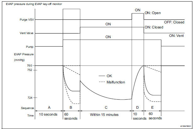
The leak detection pump creates negative pressure through the reference orifice. When the system is normal, the EVAP pressure is in 724 to 752 mmHg* and saturated within a minute.
If not, the ECM interprets this as a malfunction. The ECM will illuminate the MIL and set DTC if this malfunction is detected in consecutive drive cycle.
*: Typical valve
MONITOR STRATEGY
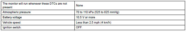
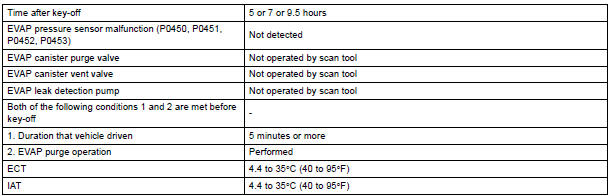
TYPICAL ENABLING CONDITIONS
Key-off monitor sequence 1 to 8
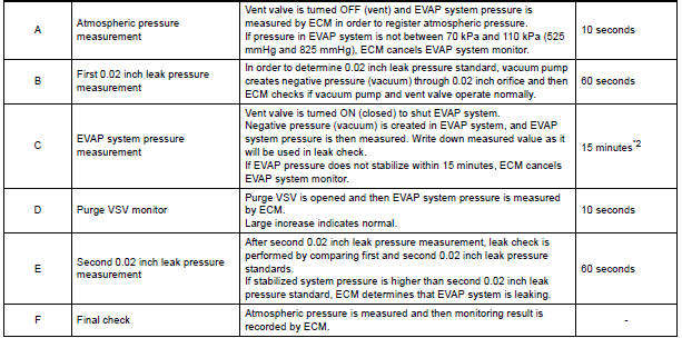
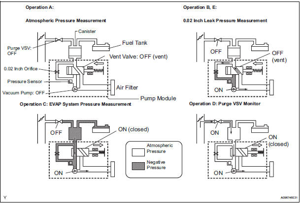
1. Atmospheric pressure measurement

2. First reference pressure measurement
3. EVAP canister vent valve close stuck check

4. Vacuum introduction

5. EVAP canister purge valve close stuck check

6. Second reference pressure measurement
7. Leak check

8. Atmospheric pressure measurement


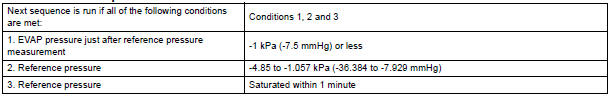
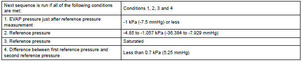
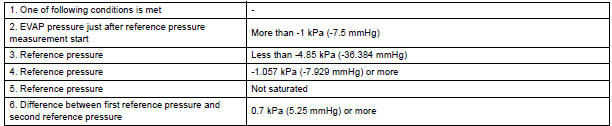
TYPICAL MALFUNCTION THRESHOLDS
MONITOR RESULT
Refer to CHECKING MONITOR STATUS
 Catalyst System Efficiency Below Threshold
DTC P0420 Catalyst System Efficiency Below Threshold
(Bank 1)
DTC P0430 Catalyst System Efficiency Below Threshold
(Bank 2)
MONITOR DESCRIPTION
The ECM uses the sensors mounted in front of and be ...
 Evaporative Emission Control System Incorrect
Purge Flow
Evaporative Emission Control System Incorrect
Purge Flow
DTC P0441 Evaporative Emission Control System Incorrect
Purge Flow
DTC SUMMARY
DESCRIPTION
The circuit description can be found in the EVAP (Evaporative Emission)
System.
INSPECTION PROCEDU ...
Other materials:
Disposal
1. DISPOSE OF FRONT SEAT OUTER BELT ASSEMBLY (WHEN INSTALLED IN VEHICLE)
NOTICE:
Never dispose of a front seat outer belt assembly
with an deactivated pretensioner.
The seat belt pretensioner produces an exploding
sound when it activates, so perform the operation
outdoors wh ...
U151f automatic transaxle
Service data
TORQUE SPECIFICATIONS
...
How to proceed with
troubleshooting
HINT:
Use these procedures to troubleshoot the power door lock
control system.
The intelligent tester should be used in steps 3 and 5.
1 VEHICLE BROUGHT TO WORKSHOP
2 CUSTOMER PROBLEM ANALYSIS
Interview the customer to confirm the trouble
3 INSPECT COMMUNICATION FUNCTI ...
