Toyota Sienna Service Manual: Evaporative Emission System Reference Orifice
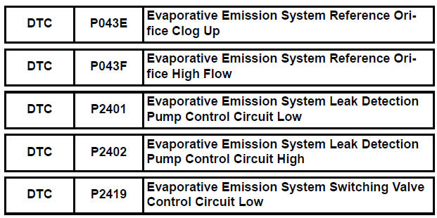
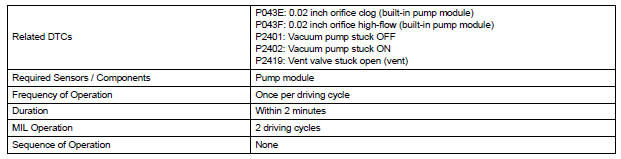
DTC SUMMARY
HINT:
The 0.02 inch orifice is located inside the pump module.
DESCRIPTION
The circuit description can be found in the EVAP (Evaporative Emission) System (See page ES-409).
INSPECTION PROCEDURE
Refer to the EVAP System (See page ES-412).
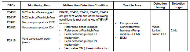
MONITOR DESCRIPTION
5 hours*1 after the ignition switch is turned off, the electric vacuum pump creates negative pressure (vacuum) in the EVAP (Evaporative Emission) system. The ECM monitors for leaks and actuator malfunctions based on the EVAP pressure.
HINT:
*1: If the engine coolant temperature is not below 35°C (95°F) 5 hours after the ignition switch is turned off, the monitor check starts 2 hours later. If it is still not below 35°C (95°F) 7 hours after the ignition switch is turned off, the monitor check starts 2.5 hours later.

*2: If there is only a small amount of fuel in the fuel tank, stabilizing the EVAP pressure takes longer than usual.
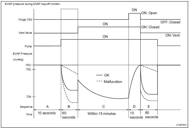
The leak detection pump creates negative pressure through the reference orifice. When the system is normal, the EVAP pressure is in 724 to 752 mmHg* and saturated within a minute.
If not, the ECM interprets this as a malfunction. The ECM will illuminate the MIL and set DTC if this malfunction is detected in consecutive drive cycle.
*: Typical valve
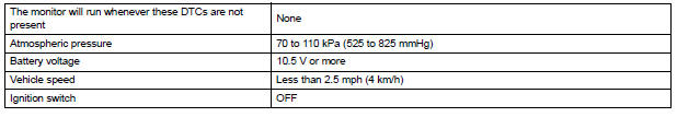
MONITOR STRATEGY
TYPICAL ENABLING CONDITIONS
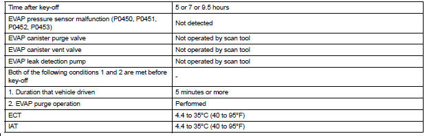
Key-off monitor sequence 1 to 8
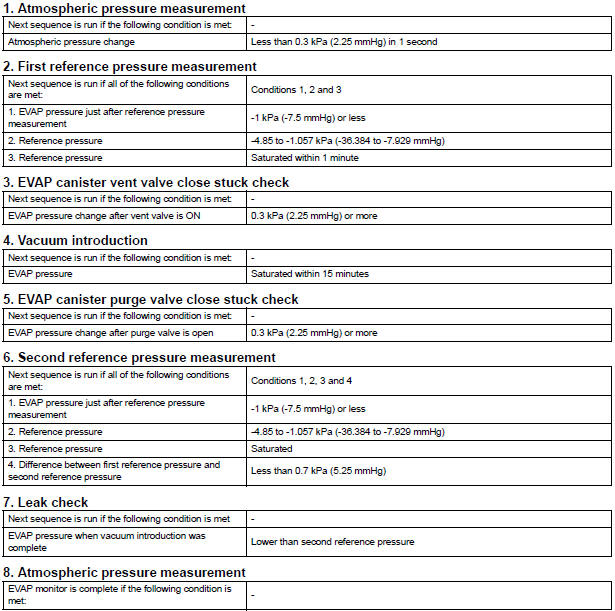

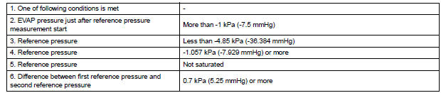
TYPICAL MALFUNCTION THRESHOLDS
MONITOR RESULT
Refer to CHECKING MONITOR STATUS (See page ES-19).
 Catalyst System Efficiency Below Threshold
MONITOR DESCRIPTION
The ECM uses the sensors mounted in front of and behind the three-way
catalyst (TWC) to monitor its
efficiency. The first sensor, an Air Fuel ratio (A/F) sensor, sends pre- ...
 Evaporative Emission Control System Incorrect Purge Flow
DTC SUMMARY
DESCRIPTION
The circuit description can be found in the EVAP (Evaporative Emission)
System (See page ES-409).
INSPECTION PROCEDURE
Refer to the EVAP System (See page ES-412).
MO ...
Other materials:
A/F sensor and ho2s monitors
(a) Preconditions
The monitor will not run unless:
2 minutes or more have elapsed since the engine
was started.
The Engine Coolant Temperature (ECT) is 75°C
(167°F) or more.
Cumulative driving time at a vehicle speed of 30
mph (48 km/h) or more exceeds 6 minutes.
Air-fuel ratio fe ...
Operation check
1. NOTICE WHEN CHECKING THE FOLLOWING
Power door lock/unlock function:
The wireless door lock control function operates
only when the following 3 conditions are met:
No key is inserted in the ignition key cylinder.
All the doors are closed.
The power door lock sys ...
Diagnosis system
1. CHECK DLC3
The vehicle's ECU uses ISO 15765-4 for
communication protocol. The terminal arrangement
of the DLC3 complies with SAE J1962 and matches
the ISO 15765-4 format.
NOTICE:
*: Before measuring the resistance, leave the
vehicle as is for at least 1 minute and do not
ope ...
