Toyota Sienna Service Manual: Evaporative Emission System Switching Valve Control Circuit High
DTC SUMMARY
DESCRIPTION
The circuit description can be found in the EVAP (Evaporative Emission) System (See page ES-404).
INSPECTION PROCEDURE
Refer to the EVAP System (See page ES-404).
MONITOR DESCRIPTION
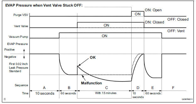
5 hours*1 after the ignition switch is turned off, the electric vacuum pump creates negative pressure (vacuum) in the EVAP (Evaporative Emission) system. The ECM monitors for leaks and actuator malfunctions based on the EVAP pressure.
HINT: *1: If the engine coolant temperature is not below 35┬░C (95┬░F) 5 hours after the ignition switch is turned off, the monitor check starts 2 hours later. If it is still not below 35┬░C (95┬░F) 7 hours after the ignition switch is turned off, the monitor check starts 2.5 hours later.
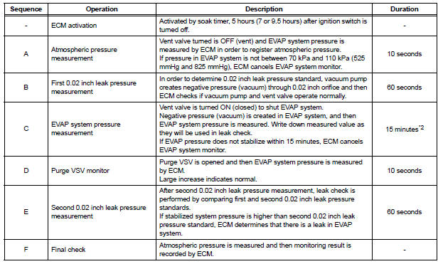
*2: If only a small amount of fuel is in the fuel tank, it takes longer for the EVAP pressure to stabilize.
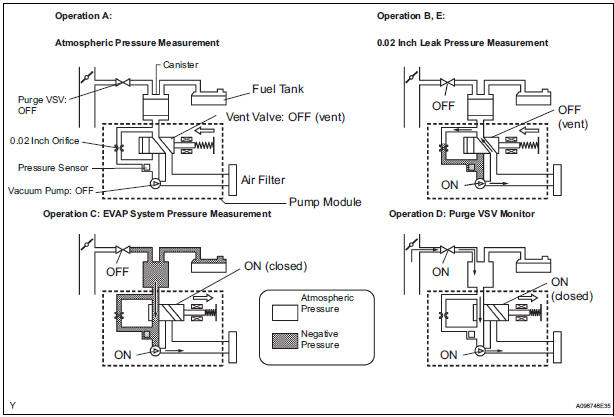
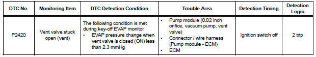
The vent valve turns ON (closes) and the EVAP (Evaporative Emission) system pressure is then measured by the ECM, using the pressure sensor, to conduct an EVAP leak check. If the pressure does not increase when the vent valve is open, the ECM interprets this as the vent valve being stuck open. The ECM illuminates the MIL and sets the DTC.
MONITOR STRATEGY
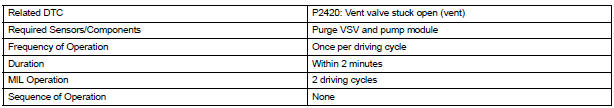
TYPICAL ENABLING CONDITIONS
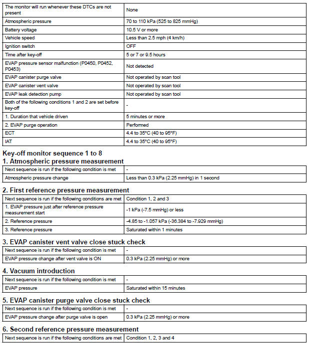
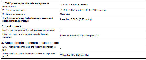
TYPICAL MALFUNCTION THRESHOLDS

MONITOR RESULT
Refer to CHECKING MONITOR STATUS (See page ES-19).
 Oxygen (A/F) Sensor Pumping Current Circuit
HINT:
Although the DTC titles say oxygen sensor, these DTCs relate to the
Air-Fuel Ratio (A/F) sensor.
Sensor 1 refers to the sensor mounted in front of the Three-Way
Catalytic Convert ...
 ECM / PCM Internal Engine Off Timer Performance
DTC SUMMARY
DESCRIPTION
To ensure the accuracy of the EVAP (Evaporative Emission) monitor values, the
soak timer, which is built
into the ECM, measures 5 hours (+/- 15 minutes) from when the ...
Other materials:
System description
1. CRUISE CONTROL SYSTEM
This system is controlled by the ECM, and is activated by
the throttle position sensor and motor. The ECM controls
the following functions: ON-OFF, - (COAST)/SET, +
(ACCEL)/RES (RESUME), CANCEL, vehicle speed
operation, motor output control, and overdrive control.
& ...
Sound Signal Circuit between Radio and Navigation Assembly and
Television Display Assembly
DESCRIPTION
The television display assembly sends an RSE sound signal to the radio and
navigation assembly through
this circuit. The sound signal that has been sent is amplified by the stereo
component amplifier, and then
is sent to the speakers.
If there is an open or short in the circuit ...
Installation
1. INSTALL INSTRUMENT PANEL SAFETY PAD SUBASSEMBLY
Using a torque wrench, install the bolt <B>.
Torque: 20 N*m (204 kgf*cm, 14 ft.*lbf)
2. INSTALL SHIFT LEVER ASSEMBLY
Using a torque wrench, install the 4 bolts.
Torque: 21 N*m (214 kgf*cm, 12.6 ft.*lbf)
3. ...
