Toyota Sienna Service Manual: Fail-safe chart
1. FAIL-SAFE
This function minimizes the loss of the ECT functions when any malfunction occurs in a sensor or solenoid.
(a) ATF (Automatic Transmission Fluid) temperature sensor: When the ATF temperature sensor has a malfunction, 5th upshift is prohibited.
(b) Counter gear speed sensor NC (Speed sensor NC): When the counter gear speed sensor has a malfunction, 5th upshift is prohibited.
(c) Shift solenoid valve DSL: When the solenoid valve DSL has a malfunction, the current to the solenoid valve is stopped.
This stops lock-up control, then fuel economy decreases.
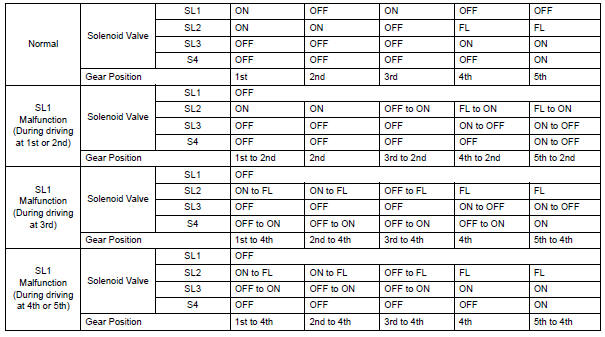
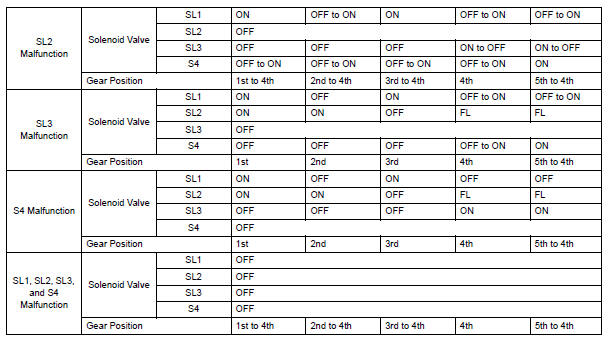
(d) Shift solenoid valve SL1, SL2, SL3 and S4: Fail safe function: If either of the shift solenoid valve circuits develops an open or short, the ECM turns the other shift solenoid "ON" and "OFF" in order to shift into the gear positions shown in the table below.
Manual shifting as shown in the following table must be done (In case of a short circuit, the ECM stops sending the current to the short circuited solenoid).
Even if starting the engine in the fail-safe mode, the gear position remains in the same position.
HINT: FL: Flex Lock-up
 Dtc clear
(A) when using the obd ii scan tool or intelligent
tester: clearing the dtcs.
(1) Connect the intelligent tester together with the
CAN VIM (controller area network vehicle
interface module) to the ...
 Data list / active test
1. DATA LIST
HINT:
Using the intelligent tester to read the DATA LIST allows
the values or states of switches, sensors, actuators and
other items to be read without removing any parts. This
non-i ...
Other materials:
On-vehicle inspection
1. INSPECT SPEEDOMETER
Check the operation.
Using a speedometer tester, check the
speedometer indication according to the table
below.
Reference: mph (U.S.A.)
Reference: km/h (Canada)
NOTICE:
Tire wear as well as over or under inflation
will cause errors.
...
Precaution
1. GENERAL PRECAUTION
When using the battery during inspection, do not
bring the positive and negative tester probes too
close to each other as a short circuit may occur.
PARTS LOCATION
SYSTEM DIAGRAM
1. SIGNAL COMMUNICATION TABLE
Driver Side Power Seat (w ...
Installation
1. REMOVE FRONT SEAT INNER BELT ASSEMBLY
HINT:
Refer to the instructions for reassembly of the front seat assembly
(for flat type).
Refer to the instructions for reassembly of the front seat assembly
(for manual seat).
Refer to the instructions for reassembly of the ...
