Toyota Sienna Service Manual: Freeze frame data
1. FREEZE FRAME DATA
(a) The vehicle (sensor) status, stored during ABS and/ or VSC operation or at the time of an error code detection, can be displayed by the intelligent tester.
(b) Only one record of freeze frame data is stored and the freeze frame data generated during ABS and/or VSC operation are updated whenever the vehicle status is changed. Also, the number of the ignition switch is ON after the freeze frame data is stored can be stored up to 31 and it can be displayed. After storing the DTC, the freeze frame data is not updated.
HINT: If the ignition switch "ON" operation exceeds 31 times, "31"appears on the display.
(c) If a malfunction occurs, the freeze frame data is stored but the ABS actuation data is deleted.
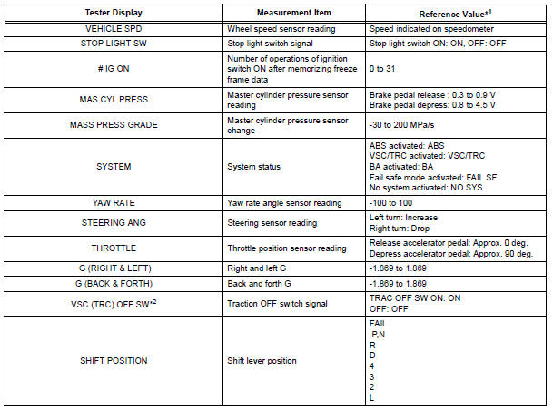
*1: If no conditions are specifically stated for "Idling", it means the shift lever is at N or P position, the A/C switch is OFF and all accessory switches are OFF.
*2: 2WD only
 Dtc check / clear
1. DTC CHECK/CLEAR (WHEN USING INTELLIGENT TESTER):
(a) DTC check
(1) Connect the intelligent tester to the DLC3.
(2) Turn the ignition switch to the ON position.
(3) Read the DTCs followi ...
 Data list / active test
1. DATA LIST
HINT:
With the intelligent tester connected to the DLC3 and the
ignition switch to the ON position, the ABS, TRAC and
VSC data list can be displayed. Follow the prompts on
the tester ...
Other materials:
Handling of hose clamps
HANDLING OF HOSE CLAMPS
(a) Before removing the hose, check the clamp position
so that it can be reinstalled in the same position.
(b) Replace any deformed or dented clamps with new
ones.
(c) When reusing a hose, attach the clamp on the
clamp track portion of the hose.
(d) For a s ...
Brake fluid
Bleeding
HINT:
If any work is performed on the brake system or if air in the
brake lines is suspected, bleed the air out of the brake
system.
NOTICE:
Wash the brake fluid off immediately if it adheres to any
painted surfaces.
1. REMOVE COWL TOP PANEL SUB-ASSEMBLY
OUTER FRONT (See page SP-13 ...
Reassembly
1. INSTALL NO. 1 COOLER THERMISTOR
(a) Install the No. 1 cooler thermistor as shown in the
illustration.
NOTICE:
Be sure to insert the thermistor only once
because reinserting it will not allow it to be
firmly secured.
When reusing the evaporator, insert the
thermistor one row ne ...
