Toyota Sienna Service Manual: Front Clearance Sonar Sensor LH Circuit
DESCRIPTION
An ultrasonic sensor consists of a sensor portion that transmits and receives ultrasonic waves and a preamplifier that amplifies them. The ultrasonic sensor outputs the ultrasonic waves and sends the received signals to the clearance warning ECU.
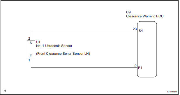
WIRING DIAGRAM
INSPECTION PROCEDURE
1 INSPECT NO. 1 ULTRASONIC SENSOR
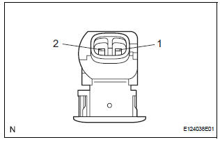
- Remove the No. 1 ultrasonic sensor.
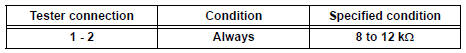
- Measure the resistance according to the value(s) in the table below.
Standard resistance
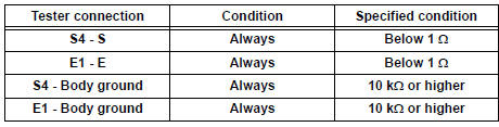
2 CHECK HARNESS AND CONNECTOR (CLEARANCE WARNING ECU - NO. 1 ULTRASONIC SENSOR)
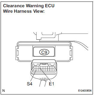
- Disconnect the C9 connector from the clearance warning ECU.
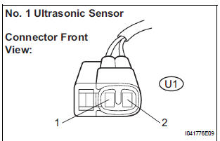
- Disconnect the U1 connector from the No. 1 ultrasonic sensor.
- Measure the resistance according to the value(s) in the table below.
Standard resistance
PROCEED TO NEXT CIRCUIT INSPECTION SHOWN IN PROBLEM SYMPTOMS TABLE
 Back Sonar Sensor RH Circuit
DESCRIPTION
An ultrasonic sensor consists of a sensor portion that transmits and receives
ultrasonic waves and a preamplifier
that amplifies them. The ultrasonic sensor outputs the ultrasonic wave ...
 Front Clearance Sonar Sensor RH Circuit
DESCRIPTION
An ultrasonic sensor consists of a sensor portion that transmits and receives
ultrasonic waves and a preamplifier
that amplifies them. The ultrasonic sensor outputs the ultrasonic wave ...
Other materials:
Diagnostic trouble code chart
If a DTC is displayed during the DTC check, check the parts
listed in the table below and proceed to the page given.
HINT:
*1: Comes on MIL (Malfunction Indicator Lamp) light up
*2: "DTC stored" mark means ECM memorizes the
malfunction code if the ECM detects the DTC detection
...
Installation
1. INSTALL AIR CONDITIONING BLOWER ASSEMBLY
(a) Install the air conditioning blower assembly with the
3 bolts.
Torque: 5.4 N*m (55 kgf*cm, 48 in.*lbf)
NOTICE:
Tighten the bolts in the order shown in the
illustration to install the air conditioning blower
assembly.
2. INSTALL AIR CONDITIO ...
No. 1 Clearance Warning Buzzer Circuit
DESCRIPTION
The clearance warning ECU receives the ultrasonic sensor signal to sound the
front warning buzzer.
WIRING DIAGRAM
INSPECTION PROCEDURE
1 INSPECT FRONT BUZZER
Remove the clearance warning ECU with front buzzer.
Apply the battery voltage to the terminals 1 and 2 o ...
