Toyota Sienna Service Manual: Front Occupant Classification Sensor LH Circuit Malfunction
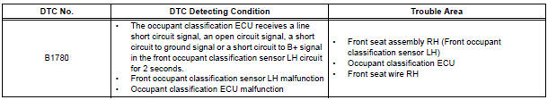
DTC B1780 Front Occupant Classification Sensor LH Circuit Malfunction
DESCRIPTION
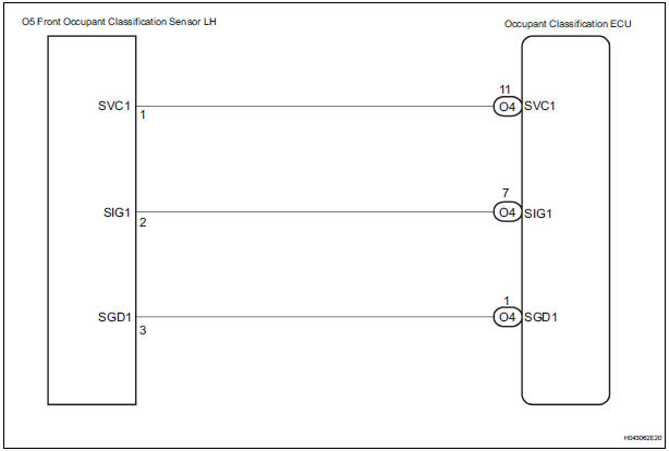
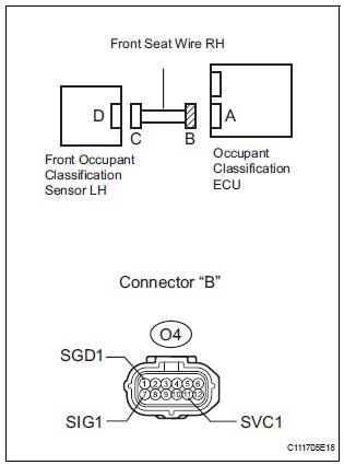
The front occupant classification sensor LH circuit consists of the occupant classification ECU and the front occupant classification sensor LH.
DTC B1780 is recorded when a malfunction is detected in the front occupant classification sensor LH circuit.
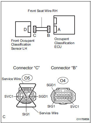
WIRING DIAGRAM
INSPECTION PROCEDURE
HINT:
- If troubleshooting (wire harness inspection) is difficult to perform, remove the front passenger seat installation bolts to see the under surface of the seat cushion.
- In the above case, hold the seat so that it does not fall down. Holding the seat for a long period of time may cause a problem, such as seat rail deformation. Hold the seat only as necessary.
1 CHECK DTC
- Turn the ignition switch to the ON position.
- Clear the DTCs stored in the memory.
HINT: First clear DTCs stored in the occupant classification ECU and then in the center airbag sensor assembly.
- Turn the ignition switch to the LOCK position.
- Turn the ignition switch to the ON position.
- Check the DTCs.
OK: DTC B1780 is not output.
HINT: Codes other than DTC B1780 may be output at this time, but they are not related to this check.
2 CHECK CONNECTION OF CONNECTORS
- Turn the ignition switch to the LOCK position.
- Disconnect the negative (-) terminal cable from the battery, and wait for at least 90 seconds.
- Check that the connectors are properly connected to the occupant classification ECU and the front occupant classification sensor LH.
OK: The connectors are properly connected.
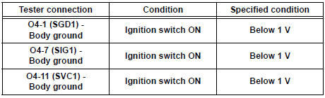
3 CHECK FRONT SEAT WIRE RH (SHORT TO B+)
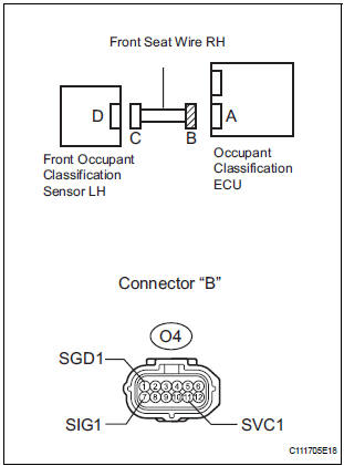
- Disconnect the connectors from the occupant classification ECU and the front occupant classification sensor LH.
- Connect the negative (-) terminal cable to the battery.
- Turn the ignition switch to the ON position.
- Measure the voltage according to the value(s) in the table below.
Standard voltage
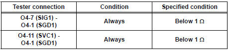
4 CHECK FRONT SEAT WIRE RH (OPEN)
- Turn the ignition switch to the LOCK position.
- Disconnect the negative (-) terminal cable from the battery, and wait for at least 90 seconds.
- Using a service wire, connect O5-1 (SVC1) and O5-3
(SGD1), and connect O5-2 (SIG1) and O5-3 (SGD1) of
connector "C".
NOTICE: Do not forcibly insert a service wire into the terminals of the connector when connecting.
- Measure the resistance according to the value(s) in the table below.
Standard resistance
5 CHECK FRONT SEAT WIRE RH (SHORT)
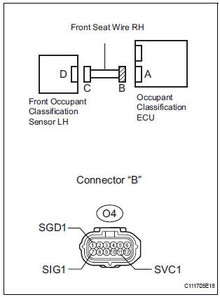
- Disconnect the service wire from connector "C".
- Measure the resistance according to the value(s) in the table below.
Standard resistance
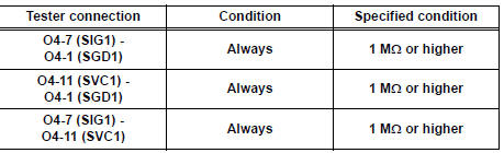
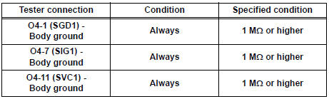
6 CHECK FRONT SEAT WIRE RH (SHORT TO GROUND)
- Measure the resistance according to the value(s) in the table below.
Standard resistance
7 CHECK DTC
- Connect the connectors to the occupant classification ECU and the front occupant classification sensor LH.
- Connect the negative (-) terminal cable to the battery.
- Turn the ignition switch to the ON position.
- Clear the DTCs stored in the memory.
HINT: First clear DTCs stored in the occupant classification ECU and then in the center airbag sensor assembly.
- Turn the ignition switch to the LOCK position.
- Turn the ignition switch to the ON position.
- Check the DTCs.
OK: DTC B1780 is not output.
HINT: Codes other than DTC B1780 may be output at this time, but they are not related to this check.
8 REPLACE OCCUPANT CLASSIFICATION ECU
- Turn the ignition switch to the LOCK position.
- Disconnect the negative (-) terminal cable from the battery, and wait for at least 90 seconds.
- Replace the occupant classification ECU.
HINT: Perform the inspection using parts from a normal vehicle if possible.
9 PERFORM ZERO POINT CALIBRATION
- Connect the negative (-) terminal cable to the battery.
- Connect the intelligent tester to the DLC3.
- Turn the ignition switch to the ON position.
- Using the intelligent tester, perform "Zero point calibration".
OK: "COMPLETED" is displayed.
10 PERFORM SENSITIVITY CHECK
- Using the intelligent tester, perform "Sensitivity check".
Standard value: 27 to 33 kg (59.52 to 72.75 lb)
11 CHECK DTC
- Turn the ignition switch to the ON position.
- Clear the DTCs stored in the memory.
HINT: First clear DTCs stored in the occupant classification ECU and then in the center airbag sensor assembly.
- Turn the ignition switch to the LOCK position.
- Turn the ignition switch to the ON position.
- Check the DTCs.
OK: DTC B1780 is not output.
HINT: Codes other than DTC B1780 may be output at this time, but they are not related to this check.
12 REPLACE FRONT SEAT ASSEMBLY RH
- Turn the ignition switch to the LOCK position.
- Disconnect the negative (-) terminal cable from the battery, and wait for at least 90 seconds.
- Replace the front seat assembly RH.
13 PERFORM ZERO POINT CALIBRATION
- Connect the negative (-) terminal cable to the battery.
- Connect the intelligent tester to the DLC3.
- Turn the ignition switch to the ON position.
- Using the intelligent tester, perform "Zero point calibration".
OK: "COMPLETED" is displayed.
14 PERFORM SENSITIVITY CHECK
- Using the intelligent tester, perform "Sensitivity check".
Standard value: 27 to 33 kg (59.52 to 72.75 lb)
END
 Passenger Side Buckle Switch Circuit Malfunction
DTC B1771 Passenger Side Buckle Switch Circuit Malfunction
DESCRIPTION
The passenger side buckle switch circuit consists of the occupant
classification ECU and the front seat
inner belt assembly ...
 Front Occupant Classification Sensor RH Circuit
Malfunction
Front Occupant Classification Sensor RH Circuit
Malfunction
DTC B1781 Front Occupant Classification Sensor RH Circuit
Malfunction
DESCRIPTION
The front occupant classification sensor RH circuit consists of the occupant
classification ECU and the
front oc ...
Other materials:
On-vehicle inspection
1. CHECK RADIATOR RESERVOIR CAP SUBASSEMBLY
a) Measure the valve opening pressure.
(1) If there are water stains or foreign matter on
rubber packings 1, 2 or 3, clean the part(s) with
water and finger scouring.
(2) Check that rubber packings 1, 2 and 3 are not
deformed, cracked or swol ...
Inspection
1. INSPECT FRONT SEAT INNER BELT ASSEMBLY RH
Release the seat belt (Buckle switch is ON).
Check the resistance between the terminals.
Standard
If the result is not as specified, replace the inner belt
assembly.
Inspect the buckle switch.
Fasten ...
Mirror Switch Circuit
DESCRIPTION
A switch signal of the outer mirror switch is transmitted to the
selected outer mirror control ECU by way
of the body ECU. Then, the outer mirror control ECU activates the mirror
motor to move the mirror UP,
DOWN, RIGHT and LEFT in response to the inputs.
HINT:
Th ...
