Toyota Sienna Service Manual: Fuel Pump Control Circuit
DESCRIPTION
The FUEL PUMP relay switches the fuel pump speed according to the engine conditions. The fuel pump operates when the ECM receives the starter-operating signal (STA) and crankshaft-rotating signal (NE).
The FUEL PUMP relay is turned ON while the engine is idling or operating at low load. This causes current to flow through the fuel pump resistor to the fuel pump. The fuel pump then operates at low speed.
The FUEL PUMP relay is turned OFF while the engine is cranking or operating at high load. The fuel pump then operates at normal speed.
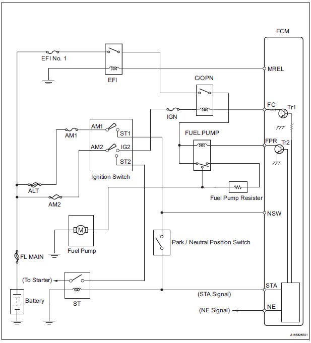
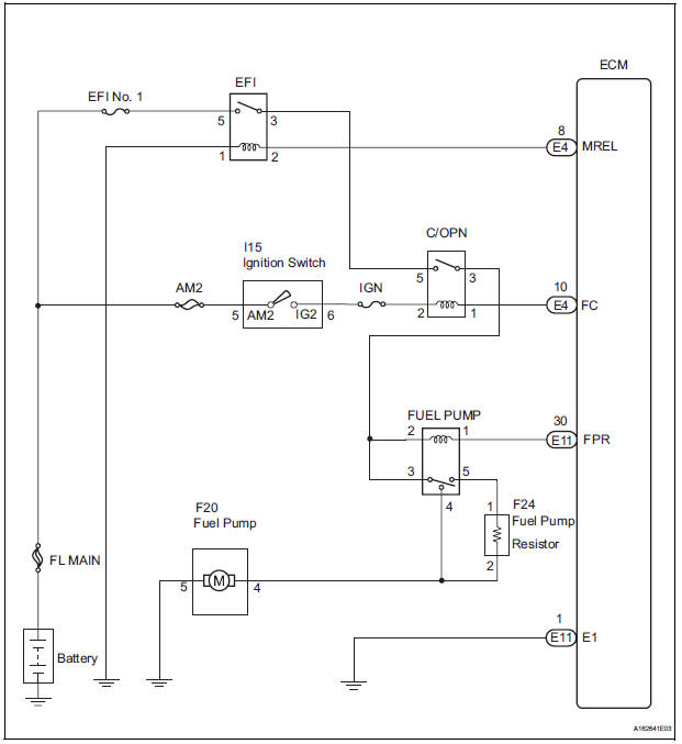
WIRING DIAGRAM
INSPECTION PROCEDURE
1 CHECK FUEL PUMP
(a) Check if there is pressure in the fuel inlet hose.
HINT:
If there is fuel pressure, the sound of fuel flowing will be heard.

2 PERFORM ACTIVE TEST BY INTELLIGENT TESTER (OPERATE C/OPN RELAY)
(a) Connect the intelligent tester to the DLC3.
(b) Turn the ignition switch to the ON position and turn the intelligent tester or the OBD II scan tool main switch on.
(c) Enter the following menus: DIAGNOSIS / ENHANCED OBD II / ACTIVE TEST / FUEL PUMP / SPD.
(d) Check the relay operation while operating it using the intelligent tester.
Standard: Operating noise can be heard from the relay.

3 INSPECT RELAY (C/OPN RELAY)
(a) Remove the C/OPN relay from the engine room junction block.
(b) Measure the resistance according to the value(s) in the table below.
Standard resistance 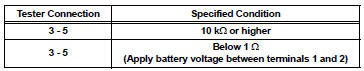
(c) Reinstall the C/OPN relay.

4 INSPECT ECM (FC VOLTAGE)
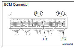
(a) Turn the ignition switch to the ON position.
(b) Measure the voltage according to the value(s) in the table below.
Standard voltage 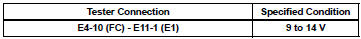

5 CHECK HARNESS AND CONNECTOR (ECM - C/OPN RELAY)
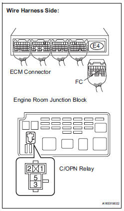
(a) Disconnect the E4 ECM connector.
(b) Remove the C/OPN relay from the engine room junction block.
(c) Measure the resistance according to the value(s) in the table below.
Standard resistance: 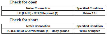
(d) Reconnect the ECM connector.
(e) Reinstall the C/OPN relay.

6 CHECK FUSE (IGN FUSE)
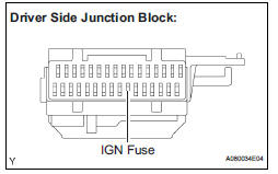
(a) Remove the IGN fuse from the driver side junction block.
(b) Measure the resistance according to the value(s) in the table below.
Standard resistance: Below 1 Ω
(c) Reinstall the IGN fuse.


7 CHECK HARNESS AND CONNECTOR (C/OPN RELAY - IGNITION SWITCH)
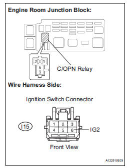
a) Reconnect the I15 ignition switch connector.
(b) Remove the C/OPN relay from the engine room junction block.
(c) Measure the resistance according to the value(s) in the table below.
Standard resistance: 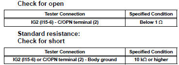
(d) Reconnect the ignition switch connector.
(e) Reinstall the C/OPN relay.

8 CHECK ECM POWER SOURCE CIRCUIT

9 INSPECT RELAY (FUEL PUMP RELAY)
(a) Remove the fuel pump relay from the engine room junction block.
(b) Measure the resistance according to the value(s) in the table below.
Standard resistance 
(c) Reinstall the fuel pump relay.

10 INSPECT FUEL PUMP
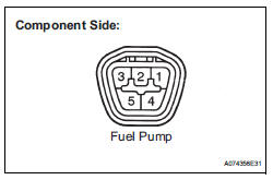
(a) Measure the resistance of the fuel pump.
(1) Measure the resistance according to the value(s) in the table below.
Standard resistance 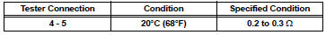
(b) Check operation of the fuel pump.
(1) Apply battery voltage to both terminals. Check that the pump operates.
NOTICE:
|

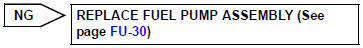
11 CHECK HARNESS AND CONNECTOR (FUEL PUMP - FUEL PUMP RELAY)
(a) Check the wire harness between the FUEL PUMP relay and fuel pump.
(1) Remove the FUEL PUMP relay from the engine room junction block.
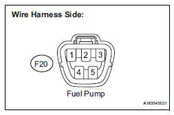
(2) Disconnect the F20 fuel pump connector.
(3) Measure the resistance according to the value(s) in the table below.
Standard resistance 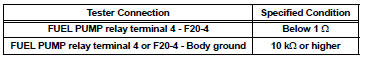

12 CHECK HARNESS AND CONNECTOR (FUEL PUMP - BODY GROUND)
(a) Check the wire harness between the fuel pump and body ground.
(1) Disconnect the F20 fuel pump connector.
(2) Measure the resistance between the terminal of the wire harness side connector and body ground.
Standard resistance 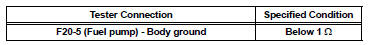
(b) Reinstall the FUEL PUMP relay.
(c) Reconnect the fuel pump connector.

13 CHECK HARNESS AND CONNECTOR (C/OPN RELAY - FUEL PUMP RELAY)
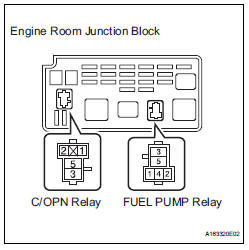
(a) Remove the C/OPN relay from the engine room junction block.
(b) Remove the FUEL PUMP relay from the engine room junction block.
(c) Measure the resistance according to the value(s) in the table below.
Standard resistance: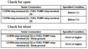
(d) Reinstall the C/OPN relay.
(e) Reinstall the FUEL PUMP relay.

14 INSPECT FUEL PUMP RESISTOR
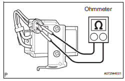
(a) Disconnect the F24 fuel pump resistor connector.
(b) Measure the resistance according to the value(s) in the table below.
Standard resistance 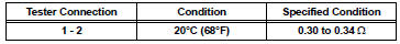
(c) Reconnect the fuel pump resistor connector.

15 CHECK HARNESS AND CONNECTOR (FUEL PUMP RELAY - FUEL PUMP RESISTOR)
(a) Disconnect the F24 fuel pump resistor connector.
(b) Remove the FUEL PUMP relay from the engine room junction block.
(c) Measure the resistance according to the value(s) in the table below.
Standard resistance: 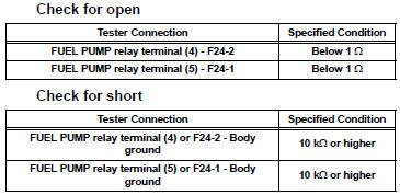
(d) Reconnect the fuel pump resistor connector.
(e) Reinstall the FUEL PUMP relay.

16 CHECK HARNESS AND CONNECTOR (FUEL PUMP RESISTOR - FUEL PUMP)
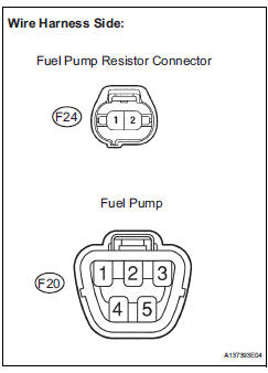
(a) Disconnect the F24 fuel pump resistor connector.
(b) Disconnect the F20 fuel pump connector.
(c) Measure the resistance according to the value(s) in the table below.
Standard resistance: 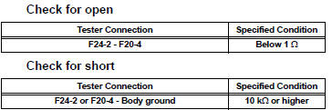
(d) Reconnect the fuel pump resistor connector.
(e) Reconnect the fuel pump connector.

PROCEED TO NEXT CIRCUIT INSPECTION SHOWN IN PROBLEM SYMPTOMS TABLE (See page ES-27)
 VC Output Circuit
DESCRIPTION
The ECM constantly uses 5 V from the battery voltages supplied to the +B
(BATT) terminal to operate the
microprocessor. The ECM also provides this power to the sensors through the VC
...
 Cranking Holding Function Circuit
DESCRIPTION
The system detects the ignition switch's starting signal (STSW) and then
supplies current to the starter
until the ECM judges that the engine has started successfully. The purpose is t ...
Other materials:
Reassembly
1. INSTALL PLANETARY GEAR
(a) Apply grease to the planetary gears and pin parts of
the planetary shaft.
(b) Install the 3 planetary gears.
2. INSTALL STARTER ARMATURE ASSEMBLY
(a) Apply grease to the plate washer and the armature
shaft.
(b) Install the starter armature to the star ...
Actuator Supply Voltage Circuit / Open
DESCRIPTION
The ECM monitors the output voltage to the throttle actuator. This self-check
ensures that the ECM is
functioning properly. The output voltage is usually 0 V when the ignition switch
is turned off. If the output
voltage is higher than 7 volts when the ignition switch is turned ...
Wiper and washer system
PRECAUTION
1. PRECAUTION OF WASHER NOZZLE ADJUSTMENT
Do not clean or adjust the washer nozzle with a
safety pin, etc. because;
the washer nozzle tip is made of resin and could
be damaged.
adjustment is not necessary because the
washer nozzle is a spray type.
...
