Toyota Sienna Service Manual: Fuel Pump Primary Circuit

DESCRIPTION
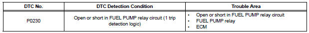
- This DTC is designed to detect a malfunction in the fuel pump (FUEL PUMP) relay circuit. When the system is normal, the battery voltage is applied to FPR terminal of the ECM while the FUEL PUMP relay is turned OFF. If the battery voltage is not applied to the FPR terminal while the FUEL PUMP relay is OFF, the ECM interprets this as a malfunction. The ECM then illuminates the MIL and sets a DTC.
- The FUEL PUMP relay switches the fuel pump speed according to the engine
conditions. The fuel
pump operates when the ECM receives the starter-operating signal (STA) and
crankshaft-rotating
signal (NE). The FUEL PUMP relay is turned ON while the engine is idling or
operating at low load.
This causes current to flow through the fuel pump resistor to the fuel pump. The fuel pump then operates at low speed. The FUEL PUMP relay is turned OFF while the engine is cranking or operating at high load. The fuel pump then operates at normal speed.
WIRING DIAGRAM
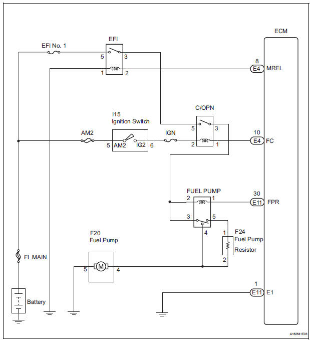
This troubleshooting procedure is based on the premise that the engine is started. If the engine is not started, proceed to the problem symptoms table (See page ES-27).
INSPECTION PROCEDURE
1 PERFORM ACTIVE TEST BY INTELLIGENT TESTER
(a) Connect the intelligent tester to the DLC3.
(b) Turn the ignition switch to the ON position and turn the intelligent tester ON.
(c) Enter the following menus: DIAGNOSIS / ENHANCED OBD II / ACTIVE TEST / FUEL PUMP SP CTL.
(d) Check the operation of the relay while operating it using the intelligent tester.
OK: Operating noise can be heard from the relay.

2 INSPECT RELAY (FUEL PUMP RELAY)
(a) Remove the FUEL PUMP relay from the engine room junction block.
(b) Measure the resistance according to the value(s) in the table below.
Standard resistance 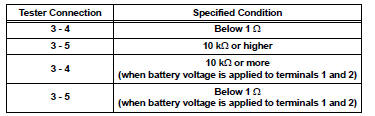
(c) Reinstall the FUEL PUMP relay.

3 CHECK HARNESS AND CONNECTOR (FUEL PUMP RELAY - ECM)
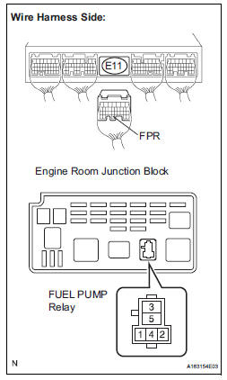
(a) Remove the FUEL PUMP relay from the engine room junction block.
(b) Disconnect the E11 ECM connector.
(c) Measure the resistance according to the value(s) in the table below.
Standard resistance 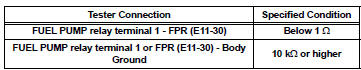
(d) Reconnect the ECM connector.
(e) Reinstall the FUEL PUMP relay

REPLACE ECM (See page ES-498)
 System Too
DESCRIPTION
The fuel trim is related to the feedback compensation value, not to the basic
injection time. The fuel trim
consists of both the short-term and long-term fuel trims.
The short-ter ...
 Random / Multiple Cylinder Misfire Detected
DESCRIPTION
When the engine misfires, high concentrations of hydrocarbons (HC) enter the
exhaust gas. High HC
concentration levels can cause increase in exhaust emission levels. Extremely ...
Other materials:
Removal
1. REMOVE CENTER REAR SEAT LAP TYPE BELT
ASSEMBLY (for 8-Passenger)
HINT:
Refer to the instructions for disassembly of the rear No. 1 seat assembly (for
center seat).
Remove the bolt and center seat lap type belt
assembly.
2. REMOVE CENTER REAR NO. 2 SEAT LAP BELT
ASSEMBLY WITH ...
Evaporative Emission Control System Leak Detected
DTC SUMMARY
DESCRIPTION
The circuit description can be found in the EVAP (Evaporative Emission)
System (See page ES-409).
INSPECTION PROCEDURE
Refer to the EVAP System (See page ES-412).
MONITOR DESCRIPTION
5 hours*1 after the ignition switch is turned off, the electric vacuum pump
c ...
Customer problem analysis
HINT:
In troubleshooting, confirm that the problem symptoms
have been accurately identified. Preconceptions should be
discarded in order to make an accurate judgment. To
clearly understand what the problem symptoms are, it is
extremely important to ask the customer about the
problem an ...
