Toyota Sienna Service Manual: Fuel tank
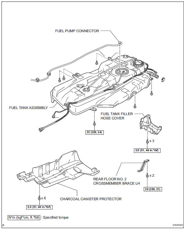
Components
REMOVAL
1. DISCHARGE FUEL SYSTEM PRESSURE (See page FU-1)
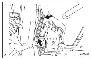
2. REMOVE CHARCOAL CANISTER PROTECTOR (See page FU-30) 3. REMOVE REAR FLOOR NO. 2 CROSSMEMBER BRACE LH
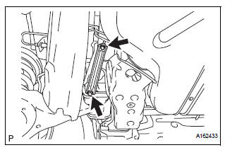
(a) Remove the 2 bolts and the rear floor No. 2 crossmember brace LH.
4. REMOVE FUEL TANK FILLER HOSE COVER
(a) Remove the 3 bolts and the fuel tank filler hose cover.
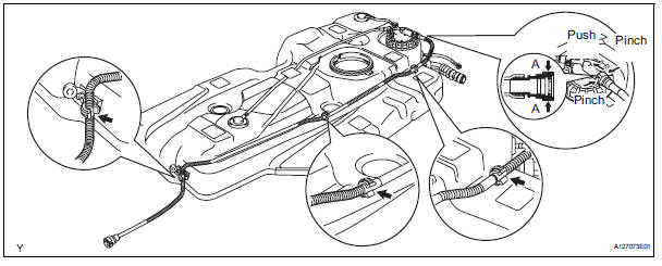
5. REMOVE FUEL TANK ASSEMBLY
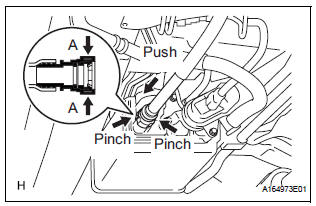
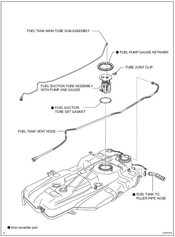
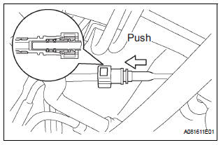
(a) Disconnect the fuel tank vent hose.
(1) Deeply push the connector to release the locking tab.
(2) Pinch portion A.
(3) Pull out the connector.
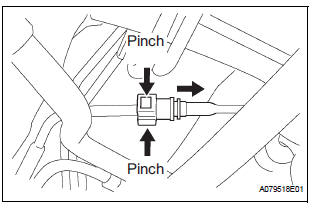
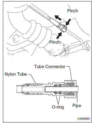
(b) Disconnect the fuel tank main tube sub-assembly.
(1) Pinch the tube connector and then pull out the fuel tank main tube sub-assembly.
NOTICE:
|
(c) Disconnect the fuel tank to filler pipe hose.
(1) Loosen the hose clamp bolt and disconnect the fuel tank to filler pipe hose.
(d) Disconnect the fuel tube.
(1) Pinch the tube connector and then pull out the fuel tank main tube sub-assembly.
NOTICE:
|
(e) Remove the 2 wire harness clamps.
(f) Set up a transmission jack under the fuel tank assembly.
(g) Remove the 6 set bolts of the 3 fuel tank bands.
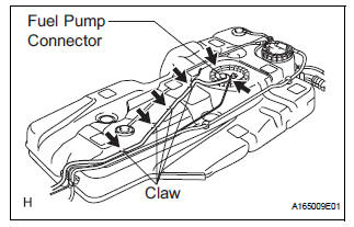
(h) While operating the transmission jack, unfasten the 4 claws for the wire harness and disconnect the fuel pump connector, then remove the fuel tank and the 3 fuel tank bands from the vehicle.
6. REMOVE FUEL TANK MAIN TUBE SUB-ASSEMBLY (See page FU-30)
7. REMOVE FUEL SUCTION TUBE ASSEMBLY WITH PUMP AND GAUGE (See page FU-31)
8. DRAIN FUEL
9. REMOVE FUEL TANK TO FILLER PIPE HOSE
(a) Loosen the hose clamp bolt and remove the fuel tank to filler pipe hose from the fuel tank.
10. REMOVE FUEL TANK VENT HOSE
(a) Remove the hose of the fuel tank vent hose from the 3 hose clamps.
(b) Remove the fuel tank vent hose.
(1) Deeply push the connector to release the locking tab.
(2) Pinch portion A.
(3) Pull out the connector.
Installation
1. CONNECT FUEL TANK VENT HOSE
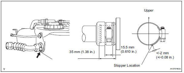
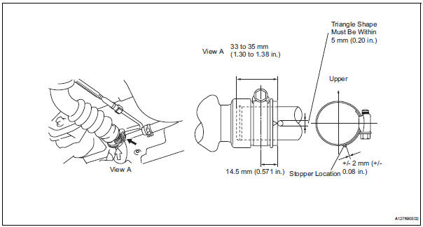
2. INSTALL FUEL TANK TO FILLER PIPE HOSE
a) Install a new fuel tank to filler pipe hose as shown in the illustration.
3. INSTALL FUEL SUCTION TUBE ASSEMBLY WITH PUMP AND GAUGE (See page FU-34) 4. INSTALL FUEL TANK MAIN TUBE SUB-ASSEMBLY (See page FU-35) 5. INSTALL FUEL TANK ASSEMBLY
(a) Set up the fuel tank assembly to the transmission jack.
(b) While operating the transmission jack, fasten the 4 claws for the wire harness and connect the fuel pump connector, then install the fuel tank and the 3 fuel tank bands to the vehicle.
(c) Tighten the 6 set bolts of the 3 fuel tank bands.
Torque: 33 N*m (336 kgf*cm, 24 ft.*lbf) (d) Install the 2 wire harness clamps.
(e) Connect the fuel tube.

(1) Push in the fuel tube connector to the pipe until fuel tube connector makes "click" sound.
NOTICE:
|
(f) Connect the fuel tank to filler pipe hose as shown in the illustration.
(g) Connect the fuel tank main tube.
(1) Push in the fuel tube connector to the pipe until fuel tube connector makes "click" sound.
NOTICE:
|
(h) Connect the fuel tank vent hose.
6. ADD FUEL
7. INSPECT FOR FUEL LEAK (See page FU-7)
8. INSTALL FUEL TANK FILLER HOSE COVER
(a) Install the 3 bolts and the fuel tank filler hose cover.
Torque: 5.0 N*m (51 kgf*cm, 44 in.*lbf)
9. INSTALL REAR FLOOR NO. 2 CROSSMEMBER BRACE LH
(a) Install the rear floor No. 2 crossmember brace LH with 2 bolts.
Torque: 28 N*m (286 kgf*cm, 21 ft.*lbf)
10. INSTALL CHARCOAL CANISTER PROTECTOR (See page FU-36)
 Fuel pump resistor
Components
REMOVAL
1. REMOVE FUEL PUMP RESISTOR
(a) Disconnect the connector.
(b) Remove the nut and fuel pump resistor.
INSPECTION
1. INSPECT FUEL PUMP RESISTOR
(a) Inspect fuel ...

Other materials:
Transfer
SST
RECOMMENDED TOOLS
EQUIPMENT
LUBRICANT
SSM
...
Data list / active test
HINT:
By accessing the DATA LIST displayed on the intelligent
tester, you can perform such functions as reading the values
of switches and sensors without removing any parts. Reading
the DATA LIST as the first step in troubleshooting is one
method to shorten labor time.
1. DATA LIST FOR CENTER ...
Active head restraints
When the occupant’s lower back
presses against the seatback during
a rear-end collision, the head
restraint moves slightly forward
and upward to help reduce the
risk of whiplash on the seat occupant
Active head restraints
Even small forces applied to the seatback may cause the head rest ...
