Toyota Sienna Service Manual: Illumination Circuit
DESCRIPTION
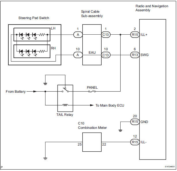
Power is supplied to the radio and navigation assembly and steering pad switch illumination when the light control switch is in the TAIL or HEAD position.
WIRING DIAGRAM
INSPECTION PROCEDURE
NOTICE: The vehicle is equipped with an SRS (Supplemental Restraint System) such as the airbags. Before servicing (including removal or installation of parts), be sure to read the precautionary notice for the Supplemental Restraint System
1 CHECK ILLUMINATION
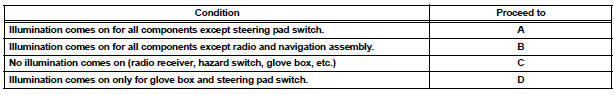
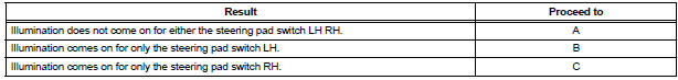
- Check if the illumination for the radio and navigation assembly, steering pad switch, glove box or others (Hazard switch, cigarette lighter, etc.) comes on when the light control switch is turned to the HEAD or TAIL position.
Result
2 CHECK HARNESS AND CONNECTOR (BATTERY - SPIRAL CABLE SUB-ASSEMBLY)
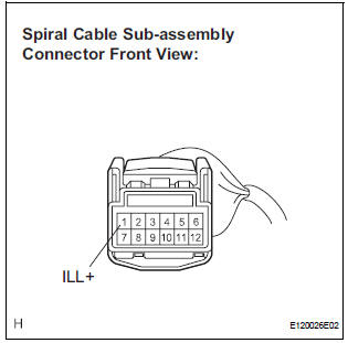
- Disconnect the spiral cable sub-assembly connector.
- Measure the voltage according to the value(s) in the table below.
Standard voltage
3 CHECK STEERING PAD SWITCH ASSEMBLY
- Disconnect the steering pad switch assembly connector.
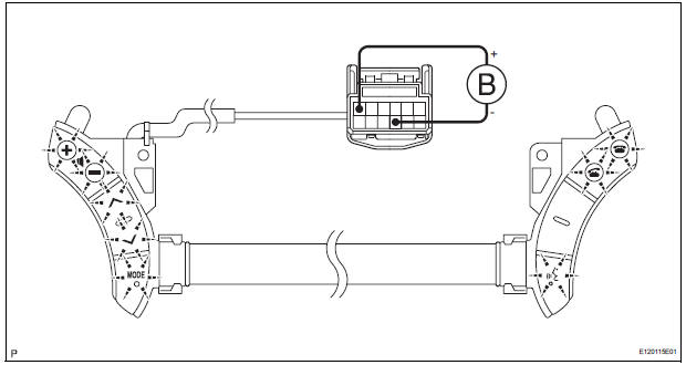
- Disconnect the steering pad switch connector.
- Connect the positive (+) lead to terminal ILL+ and the negative (-) lead to terminal EAU of the steering pad switch connector.
- Check if the illumination for the steering pad switch comes on.
4 INSPECT SPIRAL CABLE SUB-ASSEMBLY
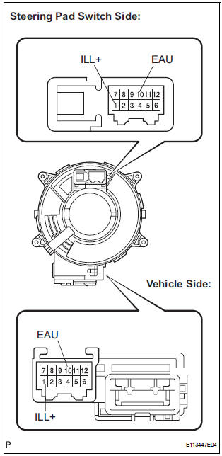
- Disconnect the steering pad switch and spiral cable subassembly connectors.
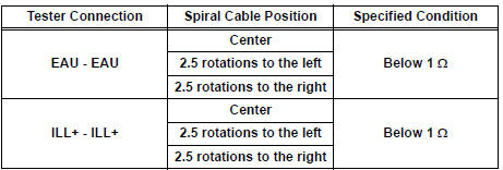
- Measure the resistance according to the value(s) in the table below.
Standard resistance
NOTICE: The spiral cable is an important part of the SRS airbag system. Incorrect removal or installation of the spiral cable may prevent the airbag from deploying. Be sure to read the page shown in the brackets
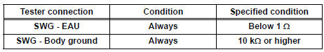
5 CHECK HARNESS AND CONNECTOR (SPIRAL CABLE SUB-ASSEMBLY - RADIO AND NAVIGATION ASSEMBLY)
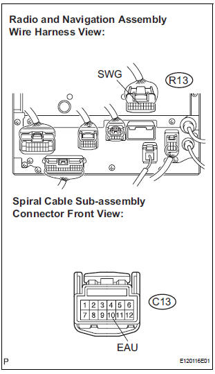
- Disconnect the connectors from the radio and navigation assembly and spiral cable sub-assembly.
- Measure the resistance according to the value(s) in the table below.
Standard resistance
REPLACE RADIO AND NAVIGATION ASSEMBLY
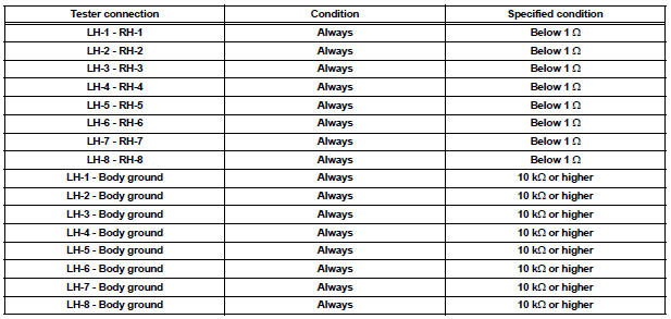
6 INSPECT STEERING PAD SWITCH CABLE
- Disconnect the steering pad switch LH and the steering pad switch RH.
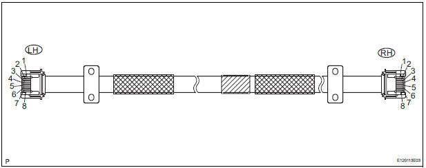
- Measure the resistance according to the value(s) in the table below
Standard resistance
REPLACE STEERING PAD SWITCH RH
7 CHECK HARNESS AND CONNECTOR (BATTERY - RADIO AND NAVIGATION ASSEMBLY)
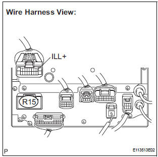
- Disconnect the radio and navigation assembly connector R15.
- Measure the voltage according to the value(s) in the table below.
Standard voltage
8 CHECK HARNESS AND CONNECTOR (RADIO AND NAVIGATION ASSEMBLY - COMBINATION METER)
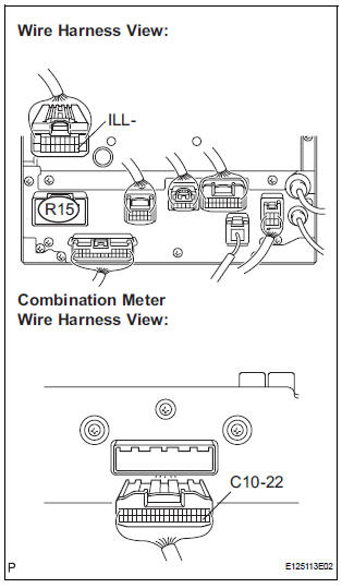
- Disconnect the radio and navigation assembly and combination meter connectors.
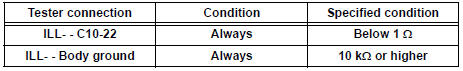
- Measure the resistance according to the value(s) in the table below.
Standard voltage
PROCEED TO NEXT CIRCUIT INSPECTION SHOWN IN PROBLEM SYMPTOMS TABLE
 Steering Pad Switch Circuit
DESCRIPTION
This circuit sends an operation signal from the steering pad switch to the
radio receiver.
If there is an open in the circuit, the navigation system cannot be operated
using the st ...
 Parking Brake Switch Circuit
DESCRIPTION
This circuit is from the parking brake switch to the radio and navigation
assembly.
WIRING DIAGRAM
INSPECTION PROCEDURE
1 CHECK BRAKE WARNING LIGHT
Check that the brake warni ...
Other materials:
Precaution
1. Before operating the power rear no. 2 seat with
stowing function, make sure that there is nothing in
the path of the seat.
CAUTION:
If someone or something is caught between the seat
and other parts, injury or damage may result.
If the system detects that the folding motor is locke ...
Route cannot be Calculated
INSPECTION PROCEDURE
1 CHECK MAP DISC
Check that the map disc is not deformed or cracked.
OK:
No deformations or cracks on map disc.
2 SET DESTINATION
Set another destination and check if the system can
calculate the route correctly.
OK:
Route can be correctly calculated.
NO ...
Stereo component amplifier
COMPONENTS
Removal
1. REMOVE GLOVE COMPARTMENT DOOR ASSEMBLY
2. REMOVE STEREO COMPONENT AMPLIFIER ASSEMBLY
Disconnect the connectors.
Remove the 2 nuts and the stereo component
amplifier assembly.
Installation
1. INSTALL STEREO COMPONENT AMPLIFIER ASSEMBLY
...
