Toyota Sienna Service Manual: Indicator Circuit
DESCRIPTION
The indicator displays the location of the obstacle and the approximate distance between the vehicle and the obstacle either by blinking or turning on.
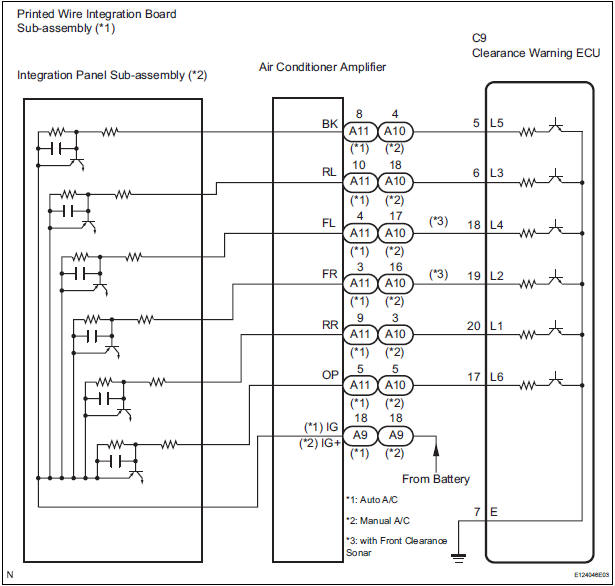
WIRING DIAGRAM
INSPECTION PROCEDURE
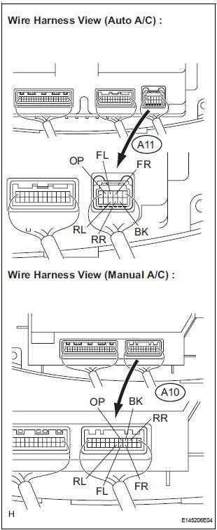
1 CHECK HARNESS AND CONNECTOR (CLEARANCE WARNING ECU - AIR CONDITIONER AMPLIFIER)
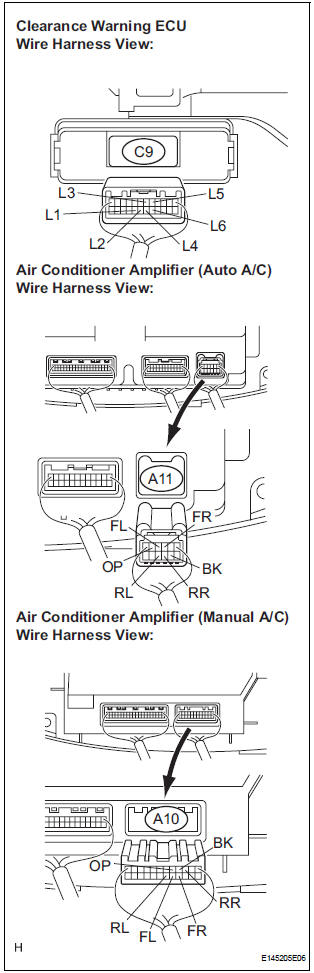
- Disconnect the connectors from the clearance warning ECU C9 and air conditioner amplifier connector A10 or A11.
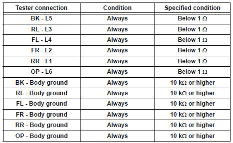
- Measure the resistance according to the value(s) in the table below.
Standard resistance
2 INSPECT INDICATOR
- Remove the integration control & panel assembly with the connectors being connected.
- Using a service wire, ground each terminal of the integration control & panel assembly connector.
- Turn the ignition switch ON.
- Check that each LED comes on.
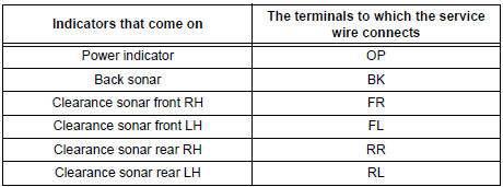
Result
PROCEED TO NEXT CIRCUIT INSPECTION SHOWN IN PROBLEM SYMPTOMS TABLE
3 INSPECT PRINTED WIRE INTEGRATION BOARD SUB-ASSEMBLY
- Check the malfunction disappears when a known good printed wire integration board sub-assembly is installed
OK: Malfunction disappears.
REPLACE PRINTED WIRE INTEGRATION BOARD SUB-ASSEMBLY
4 INSPECT INTEGRATION PANEL SUB-ASSEMBLY
- Check that the malfunction disappears when a known good integration panel sub-assembly is installed.
OK: Malfunction disappears
REPLACE INTEGRATION PANEL SUB-ASSEMBLY
 No. 2 Clearance Warning Buzzer Circuit
DESCRIPTION
The clearance warning ECU receives the ultrasonic sensor signal to sound the
rear warning buzzer.
WIRING DIAGRAM
INSPECTION PROCEDURE
1 CHECK HARNESS AND CONNECTOR (CLEARANCE WAR ...
 Horn
Horn
...
Other materials:
Types of child restraints
Child restraint systems are classified into the following 3 types
according to the age and size of the child:
Rear facing - Infant seat/convertible seat
Forward facing - Convertible seat
Booster seat
Selecting an appropriate child restraint system
Use a child rest ...
Precaution
1. HANDLING PRECAUTIONS ON STEERING SYSTEM
(a) Be careful to replace the parts properly because
they could affect the performance of the steering
system and result in a driving hazard.
2. HANDLING PRECAUTIONS ON SRS AIRBAG
SYSTEM
(a) The SIENNA is equipped with SRS (Supplemental
Restraint Sys ...
Catalyst monitor (active air-fuel ratio control
type)
(a) Preconditions
The monitor will not run unless:
The MIL is OFF.
(b) Drive Pattern
(1) Connect an intelligent tester.
(2) Turn the ignition switch to the ON position.
(3) Turn the tester or scan tool ON.
(4) Clear the DTCs.
(5) Start the engine and warm it up.
(6) Drive ...
