Toyota Sienna Service Manual: Inner rear view mirror
COMPONENTS
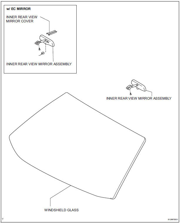
REMOVAL
1. REMOVE INNER REAR VIEW MIRROR ASSEMBLY
- w/ EC mirror: Remove the inner rear view mirror cover.
- w/ EC mirror: Disconnect the connector.
- Remove the screw.
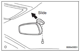
- Remove the inner rear view mirror assembly as shown in the illustration.
INSPECTION
1. INSPECT INNER REAR VIEW MIRROR ASSEMBLY
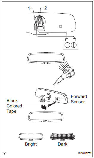
- Inspect operation of the electrochromic inner mirror.
- Connect the positive (+) lead from the battery to terminal 1 and connect the negative (-) lead to terminal 2.
- Attach black colored tape to the forward sensor to prevent it from sensing.
- Light up the mirror with an electric light and check that the mirror surface changes from bright to dark.
Standard: Mirror surface changes from bright to dark
If the result is not as specified, replace the mirror assembly.
INSTALLATION
1. INSTALL INNER REAR VIEW MIRROR ASSEMBLY
 Power mirror control system (w/o Memory)
PARTS LOCATION
Problem symptoms table
POWER MIRROR CONTROL SYSTEM
Symptom
Suspected area
Mirror does not operate
Outer mirror switch assembly
Outer r ...
 Outer rear view mirror
COMPONENTS
...
Other materials:
Seat Position Airbag Sensor Circuit Malfunction
DTC B1153/25 Seat Position Airbag Sensor Circuit Malfunction
DESCRIPTION
The seat position airbag sensor circuit consists of the center airbag sensor
assembly and the seat
position airbag sensor.
DTC B1153/25 is recorded when a malfunction is detected in the seat position
airbag sensor cir ...
What to do if... (Troubleshooting)
If there is a problem with the hands-free system or a Bluetooth®
device, first check the table below.
When using the hands-free system with a Bluetooth® device
The hands-free system or Bluetooth® device does not
work.
The connected device may not be a compatible Bl ...
ECU Power Source Circuit
DESCRIPTION
This circuit provides power to operate the theft deterrent (warning) ECU.
WIRING DIAGRAM
INSPECTION PROCEDURE
1 INSPECT FUSE (ECU-B)
Remove the ECU-B fuse from the engine room J/B.
Measure the resistance.
Standard resistance:
Below 1 Ω
2 CHECK INSTRUMENT PANEL ...
